Fluid handling systems are generally composed of mechanical equipment that generates hydraulic energy for a process that consumes that energy. The fundamental strategies to improve the efficiency of fluid handling systems are to reduce (or eliminate) the need for the hydraulic energy, to generate useful hydraulic energy more efficiently, or to use the process to produce useful energy.
The control engineer may or may not have direct responsibility for implementing these strategies, but his ability to influence the implementation of these strategies should not be underestimated.
Pay Attention to the Process
Reducing the need for hydraulic energy often entails a technical analysis of the process, which results in beneficial process changes. Control engineers are often ill prepared to perform this analysis because their training and experience lie in other areas. However, they can influence the decisions of others by simply asking thought-provoking questions:
* Can we eliminate the pump by locating the vessel upstairs and feed using gravity? This would free up space and allow us to...
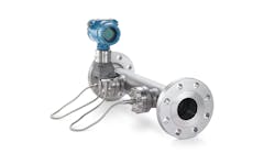
* Chilled water is used to cool a liquid to keep the flowmeter operational, but if we use a different flowmeter, which does not require cooling the fluid, then we can reduce the size of the chiller and...
* What is the maximum load required by the process? Is the equipment oversized? Smaller equipment would occupy less space, be less expensive, and cost less to operate...
* Can the fluid be obtained from another fluid handling system and eliminate the need for this equipment? That would simplify the process and make space for...
Most of the benefits cited in the above examples are not energy savings. Instead, they represent a win-win situation where the need for hydraulic energy is reduced, so energy costs are reduced. As a byproduct, the process and/or installation is improved. Reducing or eliminating the need for hydraulic energy offers one of the best strategies to reduce energy costs, but it usually requires pragmatic insight into the process and utility operation.
Minimize Pressure Drops Through Instrumentation
Another method to reduce the need for hydraulic energy is to reduce its consumption. Hydraulic energy is proportional to flow rate and pressure. In many processes, the hydraulic energy requirements to move the fluid can be reduced if the fluid flow and/or the fluid pressure are reduced.
In most applications, the flow rate must be maintained. In many applications, fluid pressure requirements can be reduced by careful instrumentation and control valve selection/sizing.
For example, it is common practice to size pumps using assumed pressure drops across the flowmeter and control valve in the piping system. In many applications, the flowmeter technology can be selected to have a negligible pressure drop, and the control valve can be sized using a pressure drop that is smaller than assumed. Such designs can potentially reduce the hydraulic requirement of the pump, in turn reducing its size and energy requirements.
Because pumps are often specified and purchased prior to specifying and purchasing instrumentation (or are part of an existing installation), these opportunities to reduce equipment and energy costs are often lost because the difference between the assumed pressure drop and the actual pressure drop is dissipated by the control valve. It is important to understand that reducing the pressure drop across the flowmeter and/or sizing the control valve for a lower pressure drop will not result in energy savings when the mechanical equipment is at the same operating point.
Consider Efficiency of Mechanical Equipment
Many influencing factors enter into the process of purchasing fluid handling equipment. One of these factors should be the efficiency of the mechanical equipment under its intended operating conditions. Note that the mechanical equipment may not (and usually does not) actually operate near its best efficiency point. For example, it is not uncommon to design centrifugal pumps to provide high pressure at relatively low flow rates. In these applications, the mechanical efficiency of the pump could be a small fraction of the efficiency at the best efficiency point of the pump.
Figure 1: Throttling Wastes Energy
In an unthrottled system, the hydraulic energy generated is equal to the hydraulic energy required (point 1). Decreasing the flow by throttling (point 2) increases the pressure above the system requirements and wastes energy.
Some equipment can use custom controls that allow the equipment to be throttled with varying degrees of energy efficiency. For example, a compressor could be controlled by bleeding off excess gas, loading and unloading the compressor, or by internal means that reduces the compression ratio. Each control strategy cited is generally more efficient than the previous strategy, however, the energy savings may or may not justify their incremental costs.
Do not be discouraged when an inefficient piece of mechanical equipment is selected. It may not always be possible to select the most energy-efficient equipment configuration because the benefits (energy and other savings) may not justify the associated costs. For example, purchasing a more efficient compressor for $1,000 instead of $200 to save $50 per year of energy may not be viable. The simple payback time associated with this installation is (1,000-200)/50 or 16 years. The time value of money will increase the payback time. Moreover, the useful life of the compressor may be only 10 years. Nonetheless, other favorable attributes of the energy-efficient compressor might more than offset the high initial purchase price.
Note that even when inefficient mechanical equipment is installed, there may be opportunities to reduce energy consumption by addressing electrical aspects of the fluid handling system.
Motor Selection Isn't Simple
The motor that drives the fluid handling system is typically the primary consumer of purchased energy. Higher-efficiency motors convert electrical energy to rotational energy in a more energy-efficient manner than standard motors. The generally accepted practice to determine the energy savings is to calculate the difference in operating costs between the two motors (weighted for anticipated operating time and load). The simple payback associated with the higher-efficiency motor can be calculated by dividing the result by the difference in cost between the motors.
However, it should be recognized that motors that are more energy efficient often exhibit less slip than a less efficient motor. This is reflected in the nameplate speed of the energy-efficient motor, which is generally higher than a standard motor.
Because energy-efficient motors generally operate faster, they can cause the mechanical equipment to produce additional hydraulic energy that is usually wasted by the process. Although the speed increase may not seem like much, the rotational energy requirement of centrifugal equipment increases as the cube of the speed, so the energy requirement can increase significantly: increasing the motor speed by 1% increases rotational energy requirements by almost 3%. In some installations, this can more than offset the increased motor efficiency, and actually increase power consumption.
Due to the additional hydraulic (and hence, mechanical) energy requirements associated with motors that exhibit less slip, the characteristics of the actual motors under consideration should be compared. Even when a standard motor is installed, or when lower slip degrades efficiency, there may be opportunities to reduce energy consumption by addressing load aspects of the fluid handling system.
Be Wary of Throttling
Even when the strategies above have been violated, there is still hope to achieve significant energy savings by reducing the rotational energy produced by the motor because, in many applications, much of the hydraulic energy developed is dissipated and wasted.
For example, in Figure 1, the pump curve represents the pressures and flows that can be generated by the pump. As flow through the pump increases, pressure tends to decrease. The system curve represents the pressure necessary to transport the fluid through the piping system and to overcome gravity and piping losses. Because piping losses increase with flow, the required pressure tends to increase as flow increases.
Using these curves, the system will operate at point 1 where the hydraulic energy generated is equal to the hydraulic energy required. Many systems, such as circulation systems, operate in this manner.
However, in many systems, it is desirable to throttle flow to meet process requirements. This is often achieved by installing a control valve in the piping to increase piping losses and shift the system curve so it intersects the pump curve at the desired flow rate. In Figure 1, the intersection of the pump curve and the throttled system curve occurs at point 2. Note that the pressure has increased (even though it is not needed), and the flow rate has decreased.
The hydraulic energy produced by the pump is proportional to pressure and flow. In this case, the pressure increases slightly whereas the flow rate decreases significantly. The net effect is a reduction in the hydraulic energy requirement. This reduces motor loading and reduces electrical energy requirements. In other words, simply throttling the flow results in energy savings.
However, note that point 2 is significantly above the system curve. This means the pump is producing much more pressure than is necessary to pump the throttled flow rate through the piping system. This excess pressure is not needed by the process and is dissipated across the control valve.
Manipulate the Pump, Not the System
Where the strategy of throttling a control valve is to manipulate the system curve to meet the pump curve at the desired flow rate, another strategy is to manipulate the pump curve to meet the system curve. Changing the fixed pump curve can be accomplished by changing internal parts, such as the size of the impeller, or by changing the size of the equipment.
In most process applications, it is desirable to control flow by manipulating the equipment curve while the process is operating. Internal mechanisms can be used to efficiently throttle some equipment during operation, or the capacity can be effectively manipulated by changing the rotational speed. This can be done with a variable-frequency drive that directly adjusts motor speed or by using a constant-speed motor with a mechanical speed reducer.
Figure 2: Speed Control Minimizes Power Consumption
The flow at Point 3 is the same as at Point 2 of Figure 1, but since point 3 is on the system curve, the pump is producing the exact amount of pressure necessary to pump the desired flow rate through the piping system.
In a centrifugal pumping system, this strategy is viable because throttling equipment speed is essentially equivalent to changing the pump curve. Therefore, because speed can be manipulated continuously during operation, the pump curve can be effectively manipulated continuously during operation. Further, pump efficiency is only somewhat degraded as speed is reduced.
Figure 2 shows the same system curve and pump curve as Figure 1. Added is a pump curve that represents lower-speed operation. The flow at point 3 is the same as at point 2 of Figure 1, but point 3 is on the system curve. This means that the pump is producing the exact amount of pressure necessary to pump the desired flow rate through the piping system. The reduced hydraulic energy requirement reduces the electrical energy required by the motor, reducing electrical energy requirements.
Even relatively small speed reductions can result in significant energy savings. For centrifugal loads, energy savings are related to the cube of the rotational speed, so operating at 90% speed results in energy savings of approximately 27%. Energy needed to operate electronic variable-speed drives can reduce these savings by a few percent. Note also that operating a variable-speed drive at full speed actually increases electrical costs due to the added energy needed to operate the drive. Calculating energy savings using variable-speed drives is not trivial (see my book, Variable Speed Drives: Principles and Applications for Energy Cost Savings, ISA Press).
Harness Electricity, Steam, and/or Heat
Another strategy is to use the process itself to produce useful forms of energy, such as generating electricity with hydroelectric dams or a gas pressure reduction, making steam from hot process gases, or harnessing heat from burning wastes. Most industrial processes do not have sufficient mass flow rate, temperature drop, heat content, and/or pressure drop to make utility generation viable. However, processes that can generate useful forms of energy can be fertile grounds for significant energy savings.
Developing strategies to find and implement energy cost savings in fluid handling systems is within the realm of control system professionals, even though they may not be in control of all of the resources and expertise necessary to analyze, design, and implement these projects. Sticking to these strategies can result in significant economic benefit and improvement of the operation.
But while it may appear that one should purchase and install only the most energy-efficient equipment and motors and operate them with variable-speed drives, this is not necessarily so. Careful studies and economic analyses should be performed to identify projects that are technically sound and economically justifiable.
David W. Spitzer, PE, is a principal partner of Spitzer and Boyes, LLC, offering engineering, product development, marketing, and distribution consulting for manufacturing and automation companies. Spitzer has more than 25 years of experience in specifying, building, installing, starting up, and troubleshooting process control instrumentation. He has developed and taught seminars for almost 20 years, is a member of ISA and the ASME MFC and ISO TC30 committees, and has published a number of books concerning the application and use of fluid handling technology. His latest, "The Consumer Guide" series, can be used to compare flowmeters by supplier. Spitzer may be reached at 845/623-1830 or e-mail [email protected].