Replacing one field transmitter technology with that of another, newer technology is usually described as easy. You pop out the old one, plumb in the new one, and there you go. In reality, it isn't as easy as all that. Many interrelated issues can jump up and surprise you.
For years, Southern Company, one of the largest electrical utilities in the U.S., relied on torque tube transmitters for determining level in the heaters and separators in the company's generating station boilers. By the mid-1990s, they determined that type of transmitter was not giving them adequate control, so they embarked on a program to replace them with guided-wave radar units.
Same Thing Only Different
Guided-wave radar units work like conventional radar, but instead of freely broadcasting the radar wave, the signal is sent down a wave guide and returns the same way.
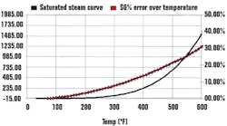
Measuring water level at temperatures and pressures along the saturated steam curve can be tough job. Application difficulties include measuring across varying process parameters and within a very corrosive environment. In high-pressure feedwater heaters, for example, the temperature/pressure is often as high as 550o F at 1028 psig (see Figure 1).
Guided-wave radar units offer better accuracy in harsh environments.
Here is where Southern Company and its vendor encountered their problem. It turned out to be a fundamental problem in basic physics.Torque-tube transmitters rely on a stable, specific gravity for accurate level measurement. A technician working on a high pressure feedwater heater knows much of the installation and calibration is done at ambient conditions (70o F at atmos) while the heater may operate at 550o F at 1028 psig. The specific gravity of water varies drastically over that range from .998 at 70o F to 0.736 at 550o F: a 25% error (see Figure 2).
Replacing one field transmitter technology with that of another, newer technology is usually described as easy. You pop out the old one, plumb in the new one, and there you go. In reality, it isn't as easy as all that. Many interrelated issues can jump up and surprise you.
For years, Southern Company, one of the largest electrical utilities in the U.S., relied on torque tube transmitters for determining level in the heaters and separators in the company's generating station boilers. By the mid-1990s, they determined that type of transmitter was not giving them adequate control, so they embarked on a program to replace them with guided-wave radar units.
Same Thing Only Different
Guided-wave radar units work like conventional radar, but instead of freely broadcasting the radar wave, the signal is sent down a wave guide and returns the same way.
Measuring water level at temperatures and pressures along the saturated steam curve can be tough job. Application difficulties include measuring across varying process parameters and within a very corrosive environment. In high-pressure feedwater heaters, for example, the temperature/pressure is often as high as 550o F at 1028 psig (see Figure 1).
Figure 1. High-Pressure EnvironmentGuided-wave radar units offer better accuracy in harsh environments.
Here is where Southern Company and its vendor encountered their problem. It turned out to be a fundamental problem in basic physics.Torque-tube transmitters rely on a stable, specific gravity for accurate level measurement. A technician working on a high pressure feedwater heater knows much of the installation and calibration is done at ambient conditions (70o F at atmos) while the heater may operate at 550o F at 1028 psig. The specific gravity of water varies drastically over that range from .998 at 70o F to 0.736 at 550o F: a 25% error (see Figure 2).
Figure 2. Temperature and Pressure-Induced Error
Extending Applications
Southern Company became very interested in guided-wave radar and its promise of excellent performance at operating conditions after configuration at ambient. They began to extend the use of guided-wave radar to other applications, including steam separators.
David Wright, a senior instrument and control specialist at Southern Company has installed several new units at Plant Gaston, a fossil-fuel unit located in Wilsonville, Ala. On the steam separator of one of the boilers, plant and vendor technicians replaced the outdated torque-tube transmitter with a Magnetrol Eclipse Model 705 transmitter and 119-in. Model 7ES steam probe. Patented, the steam probe is designed specifically for saturated steam applications. Rated to 605o F and 1,600 psi, the probe utilizes ceramic and PEEK (Poly Ether Ether Keytone) in an innovative way. The two materials act as a gradient to reduce the temperature an Aegis PF 128 O-ring seal is exposed to during operation. Note that PEEK, a high-temperature plastic, and Aegis PF 128, a perfluoroelastomer, are both compatible with steam.
"Initial results from this steam separator application were promising," Wright says. "When there was level, the unit reported it accurately. Unfortunately, we soon discovered that, instead of reporting the level as '0' inches when the water level was below the probe, the transmitter went to an "error high" condition, reporting the level as over 100%."
Bob Botwinski, from Magnetrol, elaborates. "We determined that the transmitter was not interpreting the end-of-probe signal correctly. In this particular case, the probe was appearing to be longer than its actual 119-in. length ."
David Wright continues the story. "The separator only operates during startup, and we feed live steam into it to keep it warm, so the separator was filled with live steam when it was considered empty' and the probe was seeing the steam." Magnetrol's engineers analyzed the data and soon realized that the dielectric constant of the vapor space (high- temperature saturated steam) above the water level was increasing. This increase in dielectric constant slows the propagation of the signal down the probe; which, in effect, causes the signals to appear farther out in time, i.e., appearing to be beyond the actual probe length. The dielectric constant of the vapor space can be nearly as high as 1.5 at 600o F. The guided-wave radar transmitter originally assumed the vapor space is air, which has a dielectric constant of 1.0. This change in dielectric constant could result in measurement errors of 20%! Wright had nothing but kudos for vendor team: "They came down, figured it out and fixed it quickly."
Dielectric Constants in Play
As a side note, during this analysis it was determined that the dielectric constant of the water itself changes. However, it actually decreases with increasing temperature. Water at room temperature has a dielectric constant of 80, which produces a very strong return signal. Guided-wave radar technology looks for an impedance change between the vapor/liquid interface. At room temperature, the ratio of dielectrics is very high 80:1. Unfortunately, at 600o F, the vapor space as mentioned above, has a dielectric of 1.5, while the water, which was at 80, is now at a dielectric of only 18. Obviously, this 18:1.5 ratio will produce a smaller impedance change, and therefore a smaller amplitude return signal.
Taking their cue from the use of reference targets in ultrasonic level sensors, Magnetrol fitted the guided-wave transmitter with a reference pin, so that the electronics had a physical reference to compare the interface signal to. This permitted the electronics of the transmitter to mathematically eliminate the error due to changing dielectric.
"It's worked great ever since," Wright says, "and combined with the new valve positioners, we are achieving control that we never had before with the torque tube transmitters. We never have to put it in hand' and it runs fine minimum-load to maximum-load. We've replaced all our torque tube transmitters with guided-wave radar."


