|
O |
utsourcing may be able to lower the price tags in our stores by some 25%, but the money we pay does not stay here, it pays salaries in China. The consequence is that we end up with fewer jobs here and eventually we could have fewer people who can afford even lower-priced goods from Asia.
In contrast to outsourcing, process optimization can not only improve our productivity by about the same 25%, but is likely to create good and challenging jobs. The outsource manufacturing to China road is easy, the road to regaining our competitive edge through optimized productivity is not. It takes education, professional dedication and caring about more than just the bottom line in the next quarter.
This discussion describes one of the many small steps we, as leaders process control professionals, should take on this difficult, but necessary road to recapture our competitive edge.
| RELATED ARTICLE
The Hard Road to Our Competetive Edge, Part II |
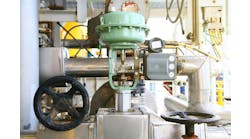
The lifetime operating cost of a pumping station is about a hundred times its initial cost, because pumping is a very energy-intensive process. For this reason, the returns on pump optimization can be substantial. If a process demands a flow of F2 at a pressure of P2 (solid system curve unthrottled in Figure 1), one can fulfill that requirement by either installing a constant speed (solid line marked 100% speed) or a variable speed pump (dashed line marked 67% speed). In order for a constant-speed pump to generate a flow of F2, it must also develop a discharge pressure of P1. Consequently, the unnecessary extra pressure (P1 - P2), which is not required to overcome the resistance of the process, must be burned up in a control valve. This not only wastes energy, but also increases the probability of valve cycling and maintenance, because cycling increases as the valve closes and because maintenance rises with pressure drop.
Process demand can be met by either wasting energy (P1-P2) or by lowering pump speed (67%).
If a variable speed pump is used, the unnecessary energy is not introduced in the first place, because the pump speed is reduced (67%) until the discharge pressure matches the process requirement (P2) that corresponds to the flow (F2) required by the process.
Optimizing Distribution
A pumping system is optimized when it meets the demand for the distributed liquid with the minimum investment of energy. When the pump station feeds a distribution header, and from that header each user meets its needs by throttling its own control valve, the total energy use will be minimized when the pressure drop across all user valves is at minimum. This occurs when the openings of all user valves are maximized and they are maximized when their inlet pressure is minimized.
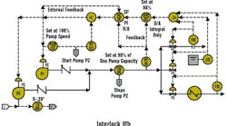
Therefore, in such an optimized control system (Figure 2) the valve position controller (VPC-02) keeps lowering the set point of PC-01 and thereby, keeps opening all user valves until the most open valve reaches a 90% open. In addition to saving energy, this control system also guarantees that no user can receive less distributed fluid than required, because no user valve is ever allowed to reach 100% open. If a coolant is distributed, the fact that no valve can fully open also increases plant safety, while keeping all valves nearly full open reduces valve cycling and maintenance.
This control system not only minimizes energy use, but also reduces valve maintenance and valve cycling, while increasing plant safety.
In this control system, VPC-2 is an integral-only controller in order to make sure that it changes the pressure controller (PC-01) set point slowly and thereby avoids oscillation. To guarantee its gradual action, the integral time of VPC-2 is set to be about 10 times that of PC-01.
The valve position controller is protected from reset windup by the external reset signal it receives from the pressure transmitter. This is essential, because otherwise it would wind up when PC-01 is switched from cascade to manual or to local control.
Stopping/starting
Figure 3 illustrates that when multiple pumps operate in parallel, their combined head-capacity curve is obtained by adding up their capacities at the same discharge head. The total capacity of multiple constant-speed pumps is found at the intersection of their combined pump curve with the system curve. The same is the case with multiple variable-speed pumps, except that they have a pump surface instead of a pump curve, because velocity is also a variable and it adds a third dimension to their personality.
The combined head-capacity curve of multiple constant-speed pumps in parallel, is the sum of their head-capacity curves. When variable speed pumps operate in parallel, their characteristic surfaces are summed in the direction of the flow coordinate.
The pump station in Figure 2 can consist of two or more variable-speed pumps. When only one pump is in operation and the pump speed approaches 100 %, the pump speed switch (PSH-03) is actuated and the second pump is started by interlock #1. When both pumps are in operation and the total flow demand drops to 90% of the capacity of a single pump, the second pump is stopped after a time delay. This 030 in. delay (TD-04) guarantees that the second pump will start only if the drop in flow demand is permanent and therefore the pump is not cycled on and off.
The top portion of Figure 2 shows the system curve and pump curves. As the capacity demand rises, the speed of the operating pump increases until (at point A) it reaches 100% and PSH-03 starts the second pump. However, if, at the time of starting the second pump, the speed-control signal was unchanged, an upset would occur, because the speed of both pumps, and therefore their discharge pressure, would instantaneously jump from point A to point C. To eliminate this temporary surge in pressure, PY-03 is provided, which drops its own output signal to x which value corresponds to the required speed, when two-pumps operate at point A.
Therefore, when interlock #1 is actuated, the low signal selector selects signal x for control and thereby provides a smooth transition. After the switching, the output signal of PY-03 slowly rises up to full scale and consequently, as soon as it exceeds the output of PIC-01, the low signal selector returns the control back to PIC-01.
Once both pumps are operating smoothly, the next control task is to stop the second pump when the load drops below the capacity of a single pump. This switching is controlled by the low flow switch FSL-05, which is set at 90 % of the capacity of one pump (point B on the systems curve).


