Ask the Experts, is moderated by noted process control authority, Béla Lipták. In this column, he and other experienced process control engineers welcome questions concerning process measurement, control and optimization. If you would like to be on our team of experts, please send a resume to [email protected].
Q: How should I minimize or maximize cavitation in control valves?
Bryant Martin
S&B Engineers and Constructors
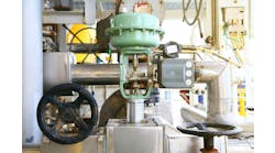
Figure 1. The greatest cavitation damage is caused by dense, pure liquids with high surface tension. The density governs the mass of the microjet stream.
(Courtesy of Hammel Dahl ConoFlow)
Figure 2. In this Swiss cheese design, small holes in the skirt or cage are arranged in pairs on opposite sides of the centerline of the valve.
(Courtesy of Hammel Dahl ConoFlow)
A:
Well, you certainly do not want to maximize cavitation! As to minimizing it, you first need to understand the phenomenon itself: Cavitation occurs when the pressure in the vena contracta region of the valve drops below the vapor pressure of the flowing fluid. This drop in pressure occurs because the high flow velocity at the vena contracta causes a localized pressure reduction. When this pressure in the vena contracta regionand only theredrops below the vapor pressure of the flowing fluid, cavitation occurs. Under these conditions of high flow velocity at the vena contracta, the pressure drops, and when it reaches the fluids vapor pressure, it causes cavities to form because the tension developed in the fluid equals its vapor pressure.The cavitation coefficient Kc is the ratio between the valve pressure drop at which cavitation starts and the difference between the inlet and the vapor pressure of the application. The allowable maximum ∆p before cavitation begins is ∆p = Kc (p1 pv). As the FL and Kc values of the different valve designs drop, the probability of cavitation increases.
Cavitation damage always occurs downstream of the vena contracta when pressure recovery in the valve causes the temporary voids to collapse. Destruction is due to the implosions that generate the extremely high-pressure shock waves in the substantially non-compressible stream. When these waves strike the solid metal surface of the valve or downstream piping, the damage gives a cinder-like appearance. Cavitation is usually coupled with vibration and a sound resembling rock fragments or gravel flowing through the valve.
Because no known material can remain indefinitely undamaged by severe cavitation, the only sure solution is to eliminate it. The greatest damage is caused by a dense pure liquid with high surface tension (e.g., water or mercury). Density governs the mass of the microjet stream. (See Figure 1).
Figure 3. Step-plug and orifice trim for liquid service. This is another valve design pattern that is less susceptible to cavitation.
(Courtesy of Masoneilan, Division of Dresser Flow Control)
Figure 4. Channel stream trim detail and valve installation. This multipath, multiturn flow design cuts down on the chances of severe cavitation.
(Courtesy of Flowserve Corp.)
In order to eliminate cavitation, one can change the process conditions. A reduction of operating temperature can lower the vapor pressure sufficiently to eliminate it. Similarly, increased upstream and downstream pressures, with ∆p unaffected, or a reduction in the ∆p can both relieve cavitation. Therefore, control valves that are likely to cavitate should be installed at the lowest possible elevation in the piping system and operated at minimum ∆p. Moving the valve closer to the pump will also serve to elevate both the up and downstream pressures. If cavitating conditions are unavoidable, one can increase operating temperature or decrease outlet pressure to cause flashing which eliminates cavitation by converting the incompressible liquid into a compressible mixture.
Where the operating conditions cannot be changed, one should use valves with a treacherous flow path with low recovery and therefore high Fc and FL coefficients and avoid high recovery valves (ball, butterfly, gate), having low FL and Fc coefficients. For example, in the Swiss cheese type design, small holes in the skirt or cage are arranged in pairs on opposite sides of the centerline of the valve. Labyrinth-type valves avoid cavitation by having a series of right-angle turns with negligible pressure recovery at each turn. Multistep or multiple valves in series can also avoid cavitation by replacing a single and deep vena contracta with several small vena contracta points as the pressure drop is distributed between several ports working in series. This solution is likely to work only if the vapor pressure of the process fluid is below the outlet pressure of the valve(s).
One can alleviate cavitation by introducing air or nitrogen into the region where cavitation is anticipated. The gas may be admitted through the valve shaft or through downstream taps on either side of the pipe in line with the shaft, and as close to the valve as possible. It also absorbs some of the pressure drop in restriction orifices, chokes, or in partially open block valves upstream or downstream of the valve.
The amount of cavitation damage is related to the sixth power of flow velocity or to the third power of pressure drop. This is the reason why reducing ∆p by a factor of 2 will result in an eight-fold reduction in cavitation destruction.
A single, fixed-opening choke fitting is applicable only when the process flow rate is constant. Choke discharges into the vapor space of a tanks will minimize cavitation damage because the bubbles will not collapse near any metallic surfaces.
While no material known to man will stand up to cavitation, some will last longer than others. The best overall selection for cavitation resistance is Stellite 6B. This is a wrought material and can be welded to form valve trims in sizes up to 3 in. (75 mm). Stellite 6 is used for hard-facing of trims and has the same chemical composition, but less impact.
A Further reading includes the ISA recommended practice ISA-RP75.32.01 and Instrument Engineers Handbook, 4th ed. Chapter 6.15.
Fred Cain
Flowserve Corporation - Flow Control Division