Q: In your book, The Instrument and Automation Engineers' Handbook, you discuss mostly liquid flow measurement and don't focus on the detection of dust-laden gas flows. My particular interest is in sealed sensors and their manufacturers. In our process, we have challenges caused by dust particles affecting total air measurement. The dust comes from recirculating lines, which serve to control dewpoint, and is fed back to the suction side of the forced draft (FD) fan during boiler start up.
Richard Mahupete,
Komati Power Station
[email protected]
Q: In my case, we seek to measure the flow in an 11 ft diameter duct carrying 1,100 °F gas with about 0.5% fine coke dust. The gas, a mixture of carbon monoxide, sulfur dioxide, amines, waste fuel gas (methane, hydrogen, etc.) and other flue gases comes from a coker at a very high velocity and is fed to a carbon monoxide boiler used as an incinerator. We have three of these ducts, each lined with 4 inches of slag.
Big swings in gas flow, which occur due to upstream process upsets, have in the past caused trips and explosions in the precipitators of the carbon monoxide boiler downstream, as well black-gas diversions for over 24 hours. I've been told that ultrasonic flowmeters don't work at high temperatures and are hindered by the slag.
Gerald Liu, P. Eng.
[email protected]
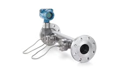
A: The above two questions are related, therefore I'll answer both together. The first application is straightforward because a standard venturi or segmental wedge (Figure 1) flow element with diaphragm seals should give good performance. Differential pressure cells with diaphragm seals (Figure 2) are marketed by many leading process instrumentation companies.
The second application is more difficult because of both the high temperature and 4 inches of slag on the duct's interior. Without knowing more about this application, I'd consider some indirect flow measurement techniques. What comes to mind is to look at the forced draft fan because the amount of work it's doing is related to the amount of gas being transported. If the FD fan is variable speed, I'd try to correlate fan speed with flow, and if it's constant speed, I'd look for correlation between flow and fan power consumption.
Béla Lipták
[email protected]
A2: You could measure fan power (not current!) to get a reasonable measure of flow. Modern motor protection relays (e.g., GE Grid Solutions’ Multilin 869 Motor Protection System) can be set up to measure power.
Simon Lucchini
[email protected]
A3: You might try using a thermal mass flow sensor that inserts into your stack connected to a transmitter.
M. Conella
[email protected]
Q: Let me introduce myself. I am Marko Katinic from Croatia and I worked in the petrochemical industry some time ago. I just read your ControlGlobal.com article, “How to prevent steam reformer tube rupture.” It's a very interesting and understandably written article. However, it's unclear to me why the "tube growth" method described is unreliable when it comes to measuring the temperature of steam reformer tubes? I kindly ask you, if you have the time and will, to answer this question.
Marko KatiNIC
[email protected]
A: The answer to this question is more completely documented in the article, “Condition assessment strategies in centrifugally cast HP steam reformer tube alloys,” presented by David Knowles, Karl Buchanan and Milo Kral. The authors indicate that “in steam methane reforming, one of the key reliability aspects relates to ensuring the integrity and reliable operation of the catalyst-filled radiant tubes. These tubes are generally exposed to metal temperatures beyond 900 °C for a considerable length of time, which makes creep the prime mode of failure.”
And it clarifies that, “Generally non-standardized materials with a range of chemistries are employed, the tubes being fabricated by centrifugal casting. This cast structure along with in-service aging is known to lead to substantial variations in creep strain/life response. Furthermore, the variation in local metal temperature along the length of individual tubes is known to be significant, so the remnant life of the tube is very sensitive to the location at which any inspection measurements are made. Temperature estimates using radiation thermometry play a key role in day-to-day management of the furnace, but this is a specialist technique and is subject to a number of potential errors. Generally, it doesn't capture the long-term trends in temperature at local regions along the tube length.”
So, summarizing, the fact that the construction of the tubes may not be perfectly even can cause errors. Furthermore, it indicates “if one considers a controlled failure process in a reformer tube, the prime ‘damage’ mechanisms relate to microstructural modification and creep.” Basically, the article indicates that high temperatures can cause varying changes in the microstructures of the metal, which in turn causes different creep responses with temperature.
As an aside, the heating source, the flame-front generators, are generally located on one side of the reformer, which will cause differences in the heating of the tubes. These small changes, as well as material fabrication differences, can cause thermal dilations that aren't uniform, and can result in measurement errors if the dilations are used to estimate temperatures correlating with tube damage.
So, as indicated by Mr. Liptak, one of the best solutions is either infrared pyrometry or the use of welded thermocouples, though this second option is generally reserved for spot measurements.
Alejandro (Alex) Varga Meder
[email protected]