This column is moderated by Béla Lipták, automation and safety consultant and editor of the Instrument and Automation Engineers' Handbook (IAEH). If you have an automation-related question for this column, write to [email protected].
Q: I'm studying your handbook about type J double ungrounded thermocouples (TC). We have two installed close together and their installation, including insertion length is the same. Normally, the temperature is between 103-109 °C. The issue we're having is happening only between 8 and 11 a.m., when one of the TCs reports 125 °C and the other 115 °C, causing a safety interlock to shut down the process. In other hours, they work well.
What would you suggest to correct this situation?
F. Alcala
[email protected]
A1: If this was a new installation, my recommendation would be to use an RTD or fiber-optic detector instead of a TC. Further, given the use of a TC, it would have been better to use a transmitter, and install it right on top of the thermowell. I understand that you don't have transmitters, and the TC signals are routed directly to their readout devices (in the control room or elsewhere). In such a case, the long extension wires can cause errors because of noise interference, guarding, shielding or grounding defects. You don't say if the lead wires from the two thermocouples are run separately or in multi-pair extension cables and whether they're individually or overall shielded or both. In my comments below I'll assume they're running separately.
In finding the cause of the error that occurs between 8 and 12 a.m., I'd first switch the readout end of the extension wires, and if by doing so the readings also switch, I'd conclude that the cause of the error is not in the readout but elsewhere. Next, I'd switch the lead wires at the sensor end, and if by so doing, the readings don't switch, the cause is probably in the extension wires. This fault could be an intermittent open circuit or contact failure at the terminal block, or an electrical noise interference.
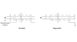
Next, I'd review the process and look for events that occur only between 8 and 12 a.m. Check if the process itself or any electrical devices in its vicinity are turned on or off only during that period, or if some vibration source is activated only in that period. In ungrounded junction designs (Figure 1), the lead wire is physically insulated from the sheath, but it's theoretically possible for an external vibration to cause the temporary opening of some contact.
The TC signal is very weak, on the order of 10 mV. In some cases, a one-degree temperature change results only a few dozen millionths of a volt change in output. Therefore, even a small amount of noise can change that output. Static noise occurs when voltage sources such as power lines are capacitively coupled to the wires. Such wires should be protected by shielding. Power lines, relays, motors, generators, etc can also cause magnetic noise. This can be minimized by twisting the wires.
Béla Lipták
[email protected]
A2: Electrical feedback, noise or ground issues can all affect the readings by TCs. I'd recommend this test to isolate faults:
- Disconnect the wires of the TC and connect them to a similar TC, but not installed in the thermowell.
- Check if there are any changes from ambient temperature; if you have noise, feedback or ground issues, the ambient TC will react in a fashion similar to the one in the thermowell.
- If the thermocouple signal holds steady with no variations, the issue could be with the thermocouple in the well.
- Verify there's no signal feedback that can cause noise or interference with the installed thermocouple.
- Finally, remove the installed thermocouple and bench test that there's no drifting of the signal.
Steps 1 and 2 will show if the TC cable has any issues. Steps 2, 3 and 4 check for external or internal faults in the TC itself. Step 5 directly verifies if the TC is in good condition or not.
Alex (Alejandro) Varga
[email protected]
A3: I suggest checking the following:
- Switch the signal lines from TC ends. If you find the problem is transferring to another loop, the issue isn't at the TC or sensor.
- Now switch over at the junction box: observe the same.
- Switch over from barrier: observe the same.
This way, you'll find out the section responsible. I suspect the issue is with grounding or the I/O channel.
Debasis Guha
[email protected]
A4: With thermocouples and RTDs, wiring is critical. For challenging applications, you might want to consider a fiber-optic temperature sensor. GaAs temperature probes are based on the inherent relationship of band gap energy to temperature. Because temperature is measured in the spectral domain, fiber-optic “wiring” has no effect on measurement accuracy.
Dennis Horwitz
[email protected]
Valve designs for liquid nitrogen
Q: We're an industrial gas company, but I design and build cryogenic freezers for the food industry. We use liquid nitrogen (LIN) in our freezers, which is -320 °F and typically 2 bar. We're reviewing which type of external valve manifold to use on our freezers based on safety considerations. In particular, we're considering the following:
- A vacuum jacketed (VJ) manifold with globe valves for both shutoff (manual and automated) and control (VJ ball valves are not available), or
- A non-VJ with ball valves for shutoff (manual and automated) and globe valve for control.
While the VJ manifolds look nice, they are expensive. Additionally, my training in the Navy (nuclear submarines) taught me that globe valves should not be used for shutoff purposes. I'd appreciate your insight on this matter.
Steve Salva
Project Engineer, Application Engineering BMTM-EA
Linde North America Inc.
[email protected]
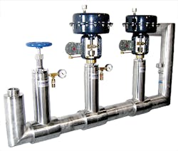
Figure 2: This vacuum-jacketed, liquid nitrogen manifold is designed for food freezer applications. (Cryocomp.com)
A: You're correct that vacuum-jacketed globe valve manifolds (Figure 2) are expensive and that globe valves don't provide tight shutoff. Some globe valve seat designs are superior, but my experience is that rotary valves are more likely to give tight shutoff.
To approach absolute zero-leakage on globe valves, coated, integral-seat, live-loaded fugitive emission, fire-safe design is needed. For absolute zero-leakage, ball valves with lapped seats are used that give tight shutoff and lower torque requirements. Also, they're tested to -196 °C (-320 °F) and tested again with water.
The main factor in designs of these valves is the coefficient of thermal contraction of seat-ring material. The seat rings shrink as they get colder, increasing operating torque and, in severe cases, causing the seat ring to split. Because plastic seat-ring materials become rigid at cryogenic temperatures, the surface finish of the seating and the sphericity of the ball are critical for seat tightness.
When designing a system, weigh the importance of cost, tight shutoff and thermal insulation. To get control quality, you have no option but to use globe valves, which are available with vacuum jackets. Your decision boils down to piping configuration and shut-off valve type. Again, the importance of cost and maintenance must be considered. If operating convenience is more important, so the control valve can be easily removed for maintenance without shut down, then two block valves and a backup control valve in the bypass are required. If cost is more important, then one block valve will do. In either case—because to my knowledge ball valves aren't available with vacuum jackets—when using ball valves, your thermal insulation will be worse.
Béla Lipták
[email protected]


