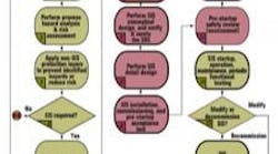
The adoption of the standard ANSI/ISA.84.01.1996, "Application of Safety Instrumented Systems for the Process Industries," and the coming IEC.61511-based ANSI/ISA.84.00.01.2004, "Functional safety: Safety Instrumented Systems for the process industry sector" have added number of "S" words to the industry's vocabulary. Examples of these words include safety instrumented systems (SIS), safety instrument function (SIF), safety integrity level (SIL), safety life cycle (SLC) and the safety requirements specification (SRS).
The SLC in the new standard ISA.84.00.01.2004 (draft), the development of the safety requirements specification comes after Step 2: "Allocation of safety functions to protection layers." In the ANSI/ISA S84.01.1996 standard, the SRS development comes just after the target SIL selection step shown in the Figure.
Why an SRS?For new systems that are to conform to S84, the SRS is part of the conformance. For a new safety system, SRS has four primary purposes:
- The SRS is the specification that defines the functionality and safety integrity requirements of the safety instrumented functions in a SIS and provides the required information to design, implement and operate the system.
- The SRS is the document that the SIF/SIS design is verified against during the design phase.
- The SRS is the specification that the safety system is validated against for the pre-startup acceptance test (PSAT), sometimes called a site acceptance test (SAT), prior to turning the system over to Operations.
- Once the SIS is operational, the SRS is a living document used to document the safety system’s current specifications during its lifetime.
By the Book
The SIS standards are performance based so the SRS’s format and style is left up to the individual company. The standards do not dictate exactly where the information needs to reside or how the information must be organized. Some companies put all their information in a single book, while other companies use a more distributed form utilizing their standard engineering documentation system, or some combination in between. In any case, the SRS should be part of the facilities’ formal engineering documentation system and placed under a formal revision process.
While there are obviously some advantages to using existing engineering documentation formats, keeping the SRS in one book provides significant advantages. The one-book format provides organization, which can help minimize errors and provide efficient usage for design, modification, review and auditing purposes.
Clear Standards
While the style and format of the SRS is left up to the implementer, the standards are reasonably clear as to what should be in the SRS, with the new ISA.84.00.01.2004 being a bit more comprehensive than the older S84 standard. This section is based on ISA.84.00.01.2004 (draft) Section 10.3 SIS Safety Requirements. The minimum required information includes:
- A description of all the safety instrumented functions (SIF).
- The safety integrity level (SIL) and mode of operation (demand/ continuous) for each safety instrumented function.
- The initiating events or sources of demand and the estimated demand rate on each safety instrumented function.
- Proof test intervals. These are the test intervals for each SIF including the definition of any online or automatic testing requirements.
- The functional relationship between each SIF process inputs and resulting outputs, including logic, timing, mathematical functions and any required permissives.
- A definition of the safe state of the process for each identified safety instrumented function.
- A definition of any individually-safe process states that, when occurring concurrently, may create a separate hazard.
- Response time requirements for the individual SIF to bring the process to a safe state.
- A description of SIS process measurements and their trip points.
- A description of SIS process output actions and the criteria for successful operation. for example, requirements for tight shut-off valves
- Manual shutdown requirements.
- A definition of energize or de-energize to trip SIF operational mode.
- Reset requirements the SIS after a shutdown.
- The maximum allowable spurious trip rate (mean time to failure spurious MTTFs or STR = 1/MTTFs).
- Failure modes and desired response of the SIF/SIS (for example, alarms, automatic shutdown, maintenance actions).
- Specific requirements related to the procedures for starting up and restarting/resetting the SIF/SIS.
- A definition of all the interfaces between the SIS and any other system (including the BPCS and operators).
- The description of the modes of operation of the plant and identification of the safety instrumented functions required to operate within each mode.
- Application software safety requirements as given in Section 12.2 of ISA.84.00.01.2004 (draft).
- Requirements for overrides/inhibits/bypasses, including how they will be cleared.
- Specification of any action necessary to achieve or maintain a safe state in the event of fault(s) being detected in the SIF/SIS.
- The mean time to repair (MTTR) which is feasible for the SIS, taking into account the travel time, location, spares holding, service contracts, environmental constraints.
- The identification of the dangerous combinations of output states of the SIF/SIS that need to be avoided.
- Identification of the extremes of all environmental conditions that are likely to be encountered by the SIF/SIS.
- Requirements to identify and take account of common cause failures.
- Identification of normal and abnormal modes for both the plant as a whole and individual plant operational procedures.
- A definition of any safety instrumented function requirements necessary to survive a major accident event.
A complete SRS is not limited to the above information and any system unique or other information which effects the design specifications, safe operation or maintenance, or the safety integrity and functionality should be put in the SRS. Also, note that the SRS information does not have to be laid out in any particular or specific order and may be combined into efficient groupings. One clear requirement is that the SRS must provide clear and comprehensive information at a suitable level of all the users of the SRS document.
References:
1. ANSI/ISA.84.01.1996, "Application of Safety Instrumented Systems for the Process Industries."
2. ANSI/ISA.84.00.01.2004, "Functional safety: Safety Instrumented Systems for the process industry sector."
Bill Mostia is principal of WLM Engineering Co., and can be reached at [email protected].


