Diagramming drum level control
To David Spitzer: Congratulations on your excellent article on drum level control, "Boiling Water is Easy as One, Two, Three, Four" (Control, Aug 2006).
Since I am the world’s greatest nit-picker, I would like to “nit-pick” a particular point in the figures—the way they show the signals from the steam flow FT and the drum LT as being combined in the LIC.
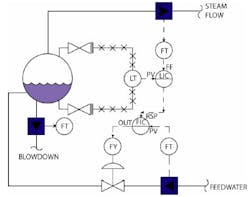
My objection to this figure (See Figure below) is the manner in which signals from the Steam Flow FT and the Drum LT are shown as both going into the LIC.
FIGURE AS IT APPEARS IN ARTICLEMy experience with many students is that, when they are interpreting a P & ID with the configuration shown, they do not understand exactly how the two transmitter signals are combined. Your drawing shows “FF” for the FT signal, but most students will miss that. They will think that the FT signal is setting the set point of the LIC.
Another lesser problem is that there is too much installation detail shown. The article is discussing control strategy, so the block valves and the lines to the LT are unnecessary—those are “instrument engineer” details, not “control strategy engineer” details.
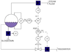
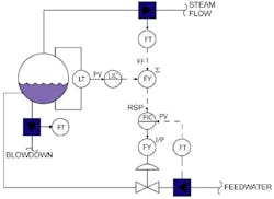
My preferred way of depicting this configuration is to show a separate summation block combining the OUTPUT of the LIC with the (FF) signal from the FT.
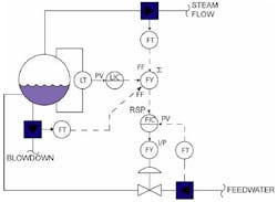
If you want to incorporate the blowdown into the control strategy, then the signal from the blowdown FT can also be incorporated into the summation block or shown as an FF signal.
FIGURE 3 IN ARTICLE: REVISED


