Greg: Dead time is a nemesis to loop performance. Given good measurements and control valves, perfect control could be possible if the dead time was zero. As detailed in most of my books and recently in ISA-TR5.9-2023, the ultimate limit to the peak error and integrated error for a load disturbance is proportional to the dead time and dead time squared, respectively. Dead-time compensators such as the Smith predictor were developed at universities over the last 50 years. Unfortunately, there’s misinformation and a lack of fundamental understanding about benefits and implementation.
We’re fortunate to talk to Héctor Henry Torres, a founding member of the ISA mentor program. He’s been a co-presenter at conferences, co-authored several articles, and is continually willing to advance knowledge in process control.
Hector, what was the method of dead-time compensation you recently used?
Héctor: I simply inserted a dead-time block in the external-reset feedback (e.g., BKCAL_IN) in my standard form PID and turned on external-reset feedback (e.g., dynamic reset limit). I didn’t have to change anything in the operator interface or implement other dynamics for dead-time compensation. A Smith predictor would’ve required me to configure and accurately set blocks for a self-regulating process, open-loop time constant and open-loop gain, which is an unnecessary complication. Also, since my application is a batch dryer, it has a
near-integrating process response. If a Smith predictor had been used, the controlled variable would no longer be the original process variable, and special configurations would be needed to restore it for the operator interface.
Greg: Simply turning on external-reset feedback (ERF) and using feedback of the manipulated variable’s response offers many other benefits noted in ISA-TR5.9-2023, including suppressing oscillations for slow, secondary control loops, control valves and variable frequency drives. A considerable override control benefit was recently realized, and detailed in the article, “The pitfalls and promises of override strategies” (Control, Feb ’23, p. 32). However, for proportional only secondary loops, the offset in the secondary loop can translate to an offset in the primary loop. This will be discussed in an upcoming Control Talk column.
What were the benefits and settings of a delayed ERF in your application?
Héctor: In reaching the batch setpoint, the overshoot and rise time were both reduced. The greatest improvement in the setpoint response was achieved when the setting of the dead-time block was about one times the actual total loop dead time. For this case, the overshoot was reduced by about 200% and the rise time by about 20%. This can translate to better batch quality and a shorter batch cycle time.
Greg: How can this be achieved? How does the ERF work?
Héctor: In essence, the ERF feature suspends the controller’s integral action if it doesn’t see a response from the manipulated output variable. The dead-time block in the ERF path is basically delaying the controlled output action that the PID sees, suspending the integral action for as long as the dead-time block is configured.
In a proportional plus integral (PI) controller, at a setpoint change, the first kick in the output comes from the controller’s proportional action. Then, the integral action begins to integrate the error and to repeat the proportional action in the time specified by the reset parameter. However, when the process exhibits enough dead time, the anticipated integration of the error is detrimental to the control because the process variable will inevitably overshoot. In this situation, it’s a widely used practice to detune the controller to minimize the overshoot, affecting the controller’s performance, nonetheless. In contrast, suspending the controller’s integral action by means of the ERF, gives the process variable the opportunity to catch up with the proportional action prior to integrating the error, minimizing overshooting and allowing the use of more aggressive and effective tuning.
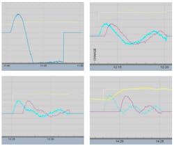
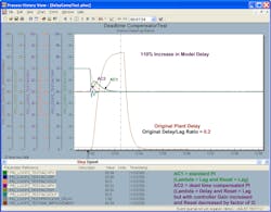
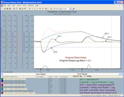
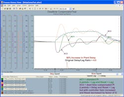
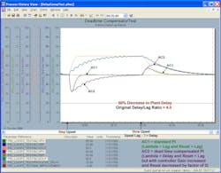
The process I applied was a near-integrating process plus lag. In the screen captures below you can see the process response at different settings.
Greg: This is consistent with what we know about dead-time compensation from tests by Peter Morgan, Greg Shinskey and me. First, the benefits are greater for setpoint changes and for processes that near-integrating and true-integrating. Also, the dead-time setting must be decreased as the time constant to dead-time ratio is decreased in self-regulating processes. For dead-time-dominant processes, a dead-time setting more than 20% larger than the actual dead time can cause rapid oscillations. This can be partly suppressed by a filter on the PID output, but with a further limitation on loop performance. The improvement in load-disturbance rejection is very small for dead-time-dominant processes, and is only seen if you don’t overestimate the dead time and greatly reduce the PID integral time.
Hector: It’s kind of ironic that the least amount of benefit is for dead-time-dominant processes and the greatest benefit is for lag-dominant (near-integrating) and true-integrating processes. The load rejection disturbance capability is great for these processes, assuming the PID is well-tuned with the PID gain appreciably increased. There are also methods of improving the setpoint response by a setpoint lead-lag, setpoint feedforward, and PID structure with two degrees of freedom.
Greg: There’s a disconnect from reality in the literature that touts the use of dead-time compensators for processes with large dead time-to-time constant ratios, which doesn’t offer a warning about how the dead-time setting must be decreased. We’re accustomed to being concerned about instability from an estimated dead time used in tuning being larger than the actual dead time but not smaller than the actual dead time. It’s disconcerting that the estimated dead time used in the model being larger than the actual dead time goes from being detrimental to beneficial as the time constant-to-dead time ratio increases. Also, the idea of going to model-based control for dead-time dominant loops is inherently flawed due to this problem and being so close to the ultimate limit to loop performance.
The widespread rule to use model predictive control (MPC) for dead-time dominant processes is even stranger. First, MPC isn’t as good as a PID for rejecting load disturbances. Also, what’s not realized is the identification of the time constant from bump and pseudo random binary sequences (PRBS) tests rapidly deteriorates to an error of 200%. Meanwhile, oscillations develop even if the time constant is correctly identified for a model dead time 40% greater than actual dead time. My 2004 ISA book, Models Unleashed—Virtual Plant and Model Predictive Control Applications, reveals these largely unrecognized limitations. Using MPC should be based on the need for multivariable process optimization and the need to simultaneously address interactions, complex reactions and multiple constraints. For dead-time-dominant systems, the delayed ERF as a dead-time compensator offers some benefit for load response and more for a setpoint response if the model dead time is not overestimated and the integral time is decreased. A better solution is feedforward and preferably ratio control for process flow disturbances. Ratio control is recommended for applications requiring feedforward multipliers or feedforward summers by feedback correction of a ratio block setpoint and bias, respectively. Ratio control enables an operator to better understand what’s going on and go to ratio control for startup and abnormal conditions. For distillation columns, ratio control is critical.
Greg: My “Advanced Application Note 3—Compensation of Dead Time in PID Controllers” offers test results on the effect of the time constant-to-dead time ratio and the error in the identified dead time for a conventional PID, a Smith Predictor, and delayed ERF PID. The PID uses the standard form with loose and tight tuning noted. These tests were conducted by me in 2006. I regret not having published these along with test results from my 2004 ISA book, Models Unleashed, in an article to help deal with the many misconceptions that are still so prevalent. Note that equations for peak and integrated error based on tuning settings don’t apply. The following excerpt from the Advanced Application Note shares some test results:
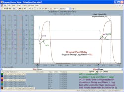
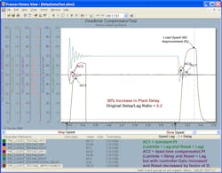
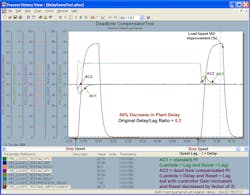
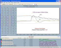
In all test results the AC1 used for comparison purposes is always an uncompensated PID tuned with a Lambda equal to the open-loop process time constant (lag). All tests have an unmeasured load disturbance at the process input. The first upset in each figure is for a step disturbance. The second upset in each figure is for a disturbance that’s been slowed down by a time constant (upset lag) that is twice the original process dead time. AC2 has Lambda set equal to the process dead time. It’s important to note that for tests with dead time compensation, the AC2 tuning is subsequently made more aggressive.
The third set of test results shows the performance of AC2, a PID with delayed external reset feedback. Like the Smith predictor, the PID gain is doubled and the reset time halved after Lambda has again been set equal to the plant delay (process dead time). In other words, this AC2, like the Smith predictor, has twice the proportional and integral action of the uncompensated AC2 in the first set of test results.
Figures 4-3a through Figure 4-3d are for a control loop with a 0.2 delay/lag ratio. The improvement in the integrated absolute error (IAE) in Figure 4-3a is about 88% over the uncompensated, conservatively tuned AC1, which is about 22% better than an uncompensated, more aggressively tuned AC2 in the first set of test results. It’s anticipated that the improvement increases as the delay/lag ratio decreases. The improvement is large enough for this dead-time compensator to be considered for low delay/lag applications, where the plant delay is accurately known. The improvement deteriorates and the response becomes oscillatory for a 50% increase in the plant delay as illustrated by Figure 4-3b. A decrease in plant delay has little as shown in Figure 4-3c. However, if the model delay is more than 100% higher than the plant delay, the PID with a delayed external reset exhibits some decaying oscillations in the controller output as shown in Figure 4-3d.
Figures 4-3e through Figure 4-3h are for a control loop with a 4.0 delay/lag ratio. The PID with a delayed external reset feedback doesn’t have the slow oscillations seen in the uncompensated, conservatively tuned AC1 for the original plant delay and 50% increase in plant delay. However, there’s a persistent, high-frequency dither in the controller output for AC2. A time constant could’ve been set in the filter block to help smooth this out. Control valve dead band and resolution limits in the control valve may help prevent these oscillations from affecting the process. If the model delay is more than 100% higher than the actual plant delay, the dither amplitude gets larger and slower as shown in Figure 4-3h.
Other possibilities exist for a more informative, external-reset signal than just the analog output (AO) block BKCAL_OUT. These include reading back actual valve position from a digital valve controller (DVC) or a secondary loop’s process variable for a cascade control loop. These alternative external reset (ER) signals may potentially be able to compensate for dynamics and failures of valves or secondary loops.

