Inverse response, negative resistance, positive feedback and discontinuities can cause processes to jump, accelerate and oscillate confusing the control system and the operator. Not properly addressing these situations can result in equipment damage and plant shutdowns besides the loss of process efficiency. Here we first develop a fundamental understanding of the causes and then quickly move on to the solutions to keep the process safe and productive.
We can appreciate how positive feedback causes problems with sound systems. We can also appreciate from circuit theory how negative resistance and positive feedback would cause an acceleration of a change in current flow. We can turn this insight into an understanding of how a similar situation develops for compressor, steam-jet ejector, exothermic reactor and parallel heat exchanger control.
The compressor characteristic curves from the compressor manufacturer that are a plot of compressor pressure rise versus suction flow shows a curve of decreasing pressure rise for each speed or suction vane position whose slope magnitude increases as the suction flow increases in the normal operating region. The pressure rise consequently decreases more as the flow increases opposing additional increases in compressor flow creating a positive resistance to flow. Not commonly seen is that compressor characteristic curve slope to the left of the surge point becomes zero as you decrease flow, which denotes a point on the surge curve, and then as the flow decreases further, the pressure rise decreases causing a further decrease in compressor flow creating a negative resistance to a decrease in flow. When the flow becomes negative, the slope reverses sign creating a positive resistance with a shape similar to that seen in the normal operating region to the right of the surge point. The compressor flow then increases to a positive flow at which point the slope reverses sign creating negative resistance. The compressor flow jumps in about 0.03 seconds from the start of negative resistance to some point of positive resistance. The result is a jump in 0.03 seconds to negative flow across the negative resistance, a slower transition along positive resistance to zero flow, than a jump in 0.03 seconds across the negative resistance to a positive flow well to the right of the surge curve. If the surge valve is not open far enough, the operating point walks about 0.5 to 0.75 seconds along the positive resistance to the surge point. The whole cycle repeats itself with an oscillation period of 1 to 2 seconds.
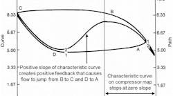
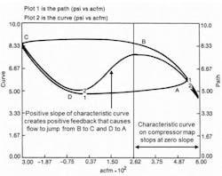
The following plot of a pilot plant compressor characteristic for a single speed shows the path 2 along the curve 1. When the operating point reaches point B, which is where the compressor characteristic curve slope is zero, the operating point jumps to point C due to the negative resistance. This jump corresponds to the precipitous drop in flow that signals the start of the surge cycle and the subsequent reversal of flow (negative acfm). After this jump to point C, the operating point follows the compressor curve from point C to point D as the plenum volume is emptied due to reverse flow. When the operating point reaches point D, which is where the compressor characteristic slope is zero again, the operating point jumps to point A due to negative resistance. If the surge valve is not opened, the operating point walks again from A to B starting the whole oscillation all over again.
Once a compressor gets into surge, the very rapid jumps and oscillations confuse the PID controller. Even a very fast PID and control valve is not fast enough. Consequently, the oscillation persists until an open loop backup holds open the surge valves until the operating point is sustained well to the right of the surge curve for about 10 seconds at which point there is a bumpless transfer back to PID control. The solution is a very fast valve and PID and an open loop backup that detects a zero slope indicating an approach to surge or a rapid dip in flow indicating an actual surge. The operating point should always be kept well to the right of the surge point.
The same shape but with much less of a dip in the compressor curve, sometimes occurs just to the right of the surge point. This local dip causes a jumping back and forth called buzzing. While the oscillation is much less severe than surge, the continual buzzing is disruptive to users.
A similar sort of dip in a curve occurs in a plot of pumping rate versus absolute pressure for a steam-jet ejector. The result is a jumping across the path of negative resistance. The solution here is a different operating pressure or nozzle design, or multiple jets to reduce the operating range so that operation to one side or the other of the dip can be assured.
Positive feedback occurs in exothermic reactors when the heat of reaction exceeds the cooling rate causing an accelerating rise in temperature that further increases the heat of reaction. The solution is to always insure the cooling rate is larger than the heat of reaction. However, in polymerization reactions the rate of reaction can accelerate so fast the cooling rate cannot be increased fast enough causing a shutdown or a severe oscillation. For safety and process performance, an aggressively tuned PID is essential where the time constants and dead time associated with heat transfer in cooling surface and thermowell and loop response are much less than the positive feedback time constant. Derivative action must be maximized and integral action must be minimized. In some cases a proportional plus derivative controller is used.
Positive feedback can also occur when parallel heat exchanges have a common process fluid input each with outlet temperature controller(s) with a setpoint close to the boiling point or temperature resulting in vaporization of a component in the process fluid. Each temperature controller is manipulating a utility stream providing heat input. The control system is stable if the process flow is exactly the same to all exchangers. However, a sudden reduction in one process flow causes overheating causing bubbles to form expanding back into the exchanger causing an increase in back pressure and hence a further decrease in process flow. The increasing back pressure eventually forces all of the process flow into the colder heat exchanger making it colder. The high velocity in the hot exchanger from boiling and vaporization causes vibration and possibly damage to any discontinuity in its path from slugs of water. When all of the water is pushed out of the hot exchanger, its temperature drops drawing feed from the cold heat exchanger that causes it to overheat repeating the whole cycle. The solution is separate flow controllers and pumps for all streams so that changes in one flow do not affect another and a lower temperature setpoint.
Acceleration in the response of a process variable is also seen as the pH approaches neutrality in a strong acid and strong base system due to the increase in process gain by a factor of 10 for each pH unit closer to neutrality (e.g., 7 pH). The result is a limit cycle across the steep portions of titration curve to the flat portions where the slope is much smaller (process gain is much smaller). The solution is to use signal characterization, excellent mixing, and very precise reagent valves.
Inverse response from changes in phase commonly seen in boiler level control occurs when increases in cold feedwater flow causes a collapse of bubbles in the downcomers causing drum level to shrink from liquid in drum falling back down into downcomers. In the opposite direction, decreases in cold feedwater flow causes a formation of bubbles in the downcomers causing drum level to swell from liquid rising up from downcomers into the drum. Preheating the feedwater can greatly reduce shrink and swell. The control solution is normally a feedforward of steam flow to feedforward flow and less feedback action in a setup called three element drum level control. However, the shrink and swell can be so large for drums too small as a result of a misguided attempt to save capital costs or as a result of pushing plant capacity beyond original design. In these cases, the direction is reversed for the very start of a feedforward signal change and is decayed out to be the right direction for the material balance. This counterintuitive action helps prevent a level shutdown but must be very carefully monitored. A warmer feedwater can make this the wrong action.
Limit cycles also develop from resolution limits typically as a result of stiction in control valves but can also originate from input cards to change speed for variable frequency drives (VFDs). Believe it or not the standard VFD input card used maybe even to this day has a resolution of only about 0.4%. Resolution limits create limit cycles that cannot be stopped unless all integrating action is removed from the process and controllers. The limit cycle period can be reduced by increasing the controller gain but the amplitude is set by the process gain.
If there are two or more sources of integrating action in a control loop, limit cycles also develop from deadband typically as a result of backlash in control valves but can also originate from deadband settings in the setup of variable frequency drives (VFDs) or configured in the split range point of controllers. The limit cycle period and amplitude can be reduced by increasing the controller gain.
Many processes have integrating action. Positioners may mistakenly have integral action. Most controllers have integrating action but it can be suspended by an integral deadband or by the use of external-reset feedback (dynamic reset limit) where there is a fast readback of actual valve position or VFD speed. For a near-integrating, true integrating or runaway process response there is a PID gain window where oscillations result from too low besides too high of a PID gain. The low PID gain limit increases as integral action increases (reset time decreases).
To summarize, to eliminate oscillations, the best solution is a design that eliminates negative resistance, inverse response, positive feedback and discontinuities. When this cannot provide the total solution, operating points may need to be restricted and the controller gain increased and integral action decreased or suspended. Not covered here are the oscillations due to resonance and interaction. In these situations, better pairing of controlled and manipulated variables is the first choice. If this is not possible, see if the faster loop can be made faster and the slower loop made slower so that the closed loop response times of the loops are different by a factor of five or more. The suspension of integral action best done by external-reset feedback can also help. The same rule and solution works for cascade control. If pairing and tuning does not solve the interaction problem, then decoupling via feedforward of one controller output to the other is needed or moving on to model predictive control.
If this gives you a headache from concerns raised about your applications, suspend thinking about the problems and use creativity and better tuning when you can actually do something.


