This column is moderated by Béla Lipták, automation and safety consultant and editor of the Instrument and Automation Engineers' Handbook (IAEH). If you have an automation-related question for this column, write to [email protected].
Q1: Dear Béla, I read your article, "Optimization of cooling towers," Nov. 19, '18, and I have a few questions.
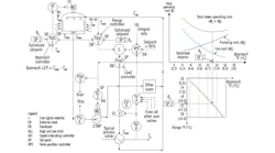
First, with reference to Figure 1, the optimum pump speed is determined by a valve position controller (VPC-4), which serves to minimize the pressure drops across all cooling water valves in the plant by opening up all of them until the most open one reaches 90% open.
Is it also feasible to determine optimum pump speed by the differential pressure across the cooling water supply and cooling water return header located near the cooling water pump area? Or perhaps the differential pressure across the cooling water supply and cooling water return header at the furthest point in the process plant?
Seer Ping
[email protected]
A1: Yes, but the tuning constants will change with location. If the safety concerns of the users differ, I usually locate the pressure taps near the most critical user.
Q2: You wrote that, "It's also recommended to use a selective control configuration, which selects the higher of the outputs of TDIC-2 and PDIC-3 to control the pump speed. This serves to prevent the supply pressure to the user valves from dropping too low."
Further, under the subject of "Optimum supply and return water temperatures" you wrote, "The load is detected by PDIC-3, and if its output is higher than that of the range controller (TDIC-2), the range controller is selected to set the pump speed. This makes sure that PDIC-3 will not drive the cooling water pressure to unsafe or undesirably high values because TDIC-2 takes over if the output of PDIC-3 is too high."
Please correct me if I'm wrong, but in comparing the above statements, you recommend using the higher of the outputs of TDIC-2 (i.e. range controller) and PDIC-3 (i.e. load controller) to control the pump speed. You also state that if the load controller output is higher than the range controller, the range controller should be used to set the pump speed. This second statement seems to contradict the first, as it implies the lower output should be selected to control the pump speed.
May I seek your advice about which control strategy should be implemented?
A2: An excellent question, it illustrates the first commandment of process control engineering, which is: In order to optimize a process, you must first fully understand it!
So, let's look at this process (Figure 1), showing the minimum cost optimization of a cooling tower-based plant cooling system. As shown in the upper right corner of the figure, the total cost of operation is the sum of the cost of operating the fan in the cooling tower (M1) and the cost of operating the pump (M2). By plotting the costs of pump and fan operation (based on actual measurements) as a function of approach (the difference between the cooling tower supply temperature and the wet bulb temperature of the air), we obtain a cost curve that has a minimum point (SP1). If we always operate the cooling system at an approach of SP1, it will run at minimum cost.
Figure 1: In cooling towers with optimization controls, if the speeds of the pumps and fans are reduced from 100% to 80%, their operating cost will be cut in half, and if their speeds are reduced to 50%, their operating cost drops to 15%.
All such systems also have an empirical relationship between the approach (SP1) and the range of the tower (SP2). The range is the difference between temperatures at which the cooling water is returned from and supplied to the plant. This empirical relationship between approach and range is shown below the cost curve. So, once determine SP1, that relationship gives the SP2 for optimized operation.
Having described the "personality" of the process, let's now look at its independent variables. They're the heat generation of the process (cooling load) and the wet bulb temperature of the air, which inversely influences tower efficiency (the lower the wet bulb temperature, the higher the efficiency). So what variables we can manipulate to match the tower operation to the cooling that the plant needs? They're the pump and fan. In case the system consists of only one pump and one fan, it's their speeds that can be manipulated. If there are multiple pumps and fans, the number in operation can be varied.
If we want to operate the total system at minimum cost, we would keep the approach controller that throttles the fan (TDIC-1) at SP1, and would keep the range controller that sets the pump speed (TDIC-2) at SP2. This would work if the cooling demand of the plant was constant—but it is not. As the load on the individual coolers vary, their temperature controllers (TIC-3 in the figure) throttle their control valves (CV-4), and the combined openings of all cooling valves determine how hard the pump must work. The cost of running these pumps drops if all valves open up, but how far can they open without losing control is usually set that at 90%. So, we select the most open cooling water valve (TY-4) and compare its opening to this 90% setpoint of the valve position controller VPC-4 to keep it there. This we achieve by assigning the load controller (PDIC-3) as the cascade slave (secondary) of VPC-4, and set the pump speed (SC-2) that way.
Now, the total system we're controlling is a heat balance system, where the heat input is the plant load and an equal amount of cooling provided by the cooling tower to match that load, while the total system is operating at minimum cost (SP1 setting SP2). The system responds to the plant load by changing the return flow to the cooling tower (Fctr), while the user valves are kept as open as possible by VPC-4 to minimize the pumping cost. This way, the cooling tower meets that load by adjusting the water supply temperature (Tctst). This means the setpoint of the cascade secondary (PDIC-3) has to be selected to serve two cascade masters (TDIC-2 and VCP-4). This selection is performed by S-5, which serves the safety of the plant by picking one or the other controller as the cascade secondary, so that on the one hand, plant equipment will not be over-pressured, and on the other, the cooling water supply temperature (Tctws) will not become too cold for some of the process coolers.
So, the answer to the apparent contradiction is that the selector (S-5) decides which cascade primary controls the cascade secondary.
Béla Lipták
[email protected]


