This column is moderated by Béla Lipták, automation and safety consultant and editor of the Instrument and Automation Engineers' Handbook (IAEH). If you have an automation-related question for this column, write to [email protected].
Q: I stumbled on www.ControlGlobal.com while searching for information about PID control of flow. This question may have been answered, but the couple of threads I found didn't seem helpful specifically for my problem. I'm controlling gas flow with a flow sensor and an electrically actuated (servo) valve positioner. The positioner is slow, taking up to 90 seconds for full travel.
I'm using a microcontroller to read the flow signal (F) and call out a control output of c(t) = Kp + Ki*[∑{e(t)*Δt}] + Kd*(ΔF/Δt). The error is e(t) = Fsp - F.
The slow positioner has been causing constant position adjustment and overshoots. I'm able to get decent control only with a huge averaging of the input flow signal (over almost a two-minute time scale). I guess we can live with it, but is there a better way?
Murthy Tata
[email protected]
A: This is a very basic and very important question. I'm glad you brought it up because, in my experience, the use and selection of positioners is the cause of the most frequent control problems. (The other error seen most often is usually caused by valve response.)
The answer to your question applies to all cascade systems. The slave controller in all cascade control loops must be faster than the master controller. No exception! This is kind of self-evident from everyday life. After all, how could, say, a pilot do his/her job if the second pilot was still busy carrying out the previous order when the next was given?
People often don’t realize that a positioner is a slave controller, with all its advantages and limitations. It can both help and hurt the performance of the loop. Therefore, I'll give a brief discussion of the subject of positioners before giving my advice concerning your specific question.
The purpose of a positioner is to improve the accuracy and response of control valves. This means it will help to have the valve position more closely approach the position commanded by the controller. A positioner can reduce the effects of many dynamic variations. These include changes in packing friction due to dirt, corrosion, lubrication or lack of lubrication; variations in the dynamic forces of the process; sloppy linkages (causing dead band); and nonlinearities in the valve actuator.
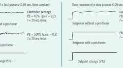
Figure 1: In slow processes (right), a positioner always improves loop performance, but in fast processes (left), particularly if the controller is pneumatic and the process is faster than the positioner, it can hurt loop performance.
The dead band of a good valve/actuator is up to 5%. Large plug valves and ball valves with less than perfect linkages and inadequate actuators may be far worse. A better positioner with the proper actuator can often reduce the dead band to less than 0.5% of stroke.
A pneumatic positioner increases the actuator speed or thrust by increasing the actuator pressure and/or air flow volume, and can modify the valve characteristics through the use of mechanical links and cams or by electronic function generators. While these positioner capabilities are very important, some of these capabilities can also be obtained or approximated with other accessories.
The positioner/actuator combination is the secondary control loop in a cascade system, receiving its setpoint from the master controller. For a cascade secondary to improve control, it must respond more quickly than the primary loop. The ideal situation would be if the time constant of the secondary was one-tenth (open-loop speed of response 10 times as fast) of that of the primary (but certainly less than half). No process control response time can be faster than the slowest element in the control loop, therefore, the performance of a cascade system improves with fast secondary response.
It’s clear that poor valve response reduces the quality of control much more than one would expect. If that’s the case, the controller tuning must be modified (gain reduced, integral lengthened) to avoid oscillation due to dead band and response delay. In typical real applications, controller tuning is conservative and avoids any hint of oscillation, and therefore response is even worse than it it could be. (Operators usually object to cycling processes.)
Figure 1 illustrates a fast flow process, where the loop without a positioner can be tuned more tightly (for higher gain and more repeats/minute). Such a loop responds better without a poor positioner. It might also be noted that after a new state is reached, the positioned installation gives better and noisier control because of increased speed of response.
Electric actuators are used where air isn't available and where their typically slow operating speed is acceptable. There are some specialized electric valve actuators that can provide very high position precision; others can provide reasonably fast response.
Sorry for taking so long to come to an answer to your question, but I believe it’s useful to understand the cascade nature of positioning, as described above. So, turning to your specific question, assuming that your valve is linear and you have no derivative in your controller, you can disconnect the positioner. Or if the positioner is an integral part of the actuator, insert a lag into the controller output to make its time constant at least double that of the positioner.
Another option is to use gap control, where as long as the flow is inside the gap, the controller stays inactive. Today’s microprocessor controllers provide broad tuning adjustment ranges, so you can set the controller gain much lower (portional band wider) and leave the integral (reset) fast to match the time constant of your relatively fast flow process.
Béla Lipták
[email protected]
A: I have few follow-up questions before I can guide you for a reasonably stable tuning. Which software PID block are you using? Is it PID_IND or PID_ISA block? Or are you doing your own logic? Have you done a step test? I've tuned liquid flow control, and we don’t use D, but for gas, you'll need to use D gain.
Another problem I've seen is the range for the transmitter. What is the inherent deadband of your positioner? Discuss it with the manufacturer of the positioner, and ensure that the setup/configuration is appropriate for your application.
Hiten A. Dalal PE
PMP Automation Engineer
[email protected]
A: Yes, there is a better way to do flow control, but it would require that you replace the slow-acting electric control valve actuator with a pneumatic or a direct-acting, electric solenoid-type control valve actuator. What you describe is not a solenoid actuator but a reversible electric motor driving the control valve position through a screw-thread mechanical linkage. These have been in use for many years to control very large objects, such as air dampers in boilers, but are not suitable for gas or liquid flow control.
If your actuator is more like a large air damper rather than a control valve, then you'd probably benefit from using a gap-action control algorithm or an error-squared control algorithm. These algorithms have a characteristic of taking little action when the measured value is close to the setpoint. Both algorithms are common variants of the PID algorithm you seem to be using, and are commonly found in the algorithms of most DCSs and even most PLCs used for closed-loop control.
Most process control textbooks also discuss these variations of PID control. The gap-action controller is simple: establish a zone around the setpoint and when the error is within this gap, don’t change the controller output. The error-squared controller is more complicated, and you can find a discussion at this website: https://pdfs.semanticscholar.org/921e/c98836dda49347d1d99f6a751b548b475283.pdf.
Richard H. Caro
CEO, CMC Associates, ISA Life Fellow
[email protected]

Leaders relevant to this article:


