Editor’s note: This column is moderated by Béla Lipták, who is also the editor of the Instrument and Automation Engineers’ Handbook (5th edition). If you have a question concerning measurement, control, optimization or automation, please send it to [email protected]. When you send a question, please include full name, affiliation and title.
Q: Can a resistive temperature detector (RTD) signal be split?
I have a pt100 sensor with one output. I need to split this output into two signals to connect them to RTD input of two modules.
Rahim Salamat, I&C senior engineer, Bakhtar Group

A1: You didn’t state if your installation is a two-, three- or four-wire RTD, so I’ll first assume that you want to send three-wire inputs into both modules. In Figure 1, lead wire C acts as a sense lead and is part of both halves of the bridge, while wires A and B are part of the two halves of the bridge. At null balance, R3 equals B – A + RTD. Therefore, the lead-wire error is no longer the sum of their resistances (A + B), but only the difference between them (B – A).

This is a major improvement compared to a two-wire installation because it reduces the lead-wire error, if the outer legs are the same, but corrosion and loose connections can still create significant resistance differences between the legs. It reduces, but does not eliminate it, because wire resistances are only within a ±10% tolerance. Therefore, if A and B are identical wires of identical lengths, their resistances can still differ within that tolerance.
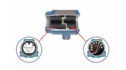
If nominally both leads are 5 Ω, one could be 4.5 Ω and the other 5.5 Ω and their resistance difference of a 100-Ω platinum RTD could be 1.0 Ω causing an error of up to 1/0.385 = 2.6 °C. This can be of particular significance if the lead wires are long or when the transmitter span is narrow. For example, if 0.25% accuracy is required and the measuring span is 10 °F (5.6 °C), this error limit would only be 0.025 °F (0.014 °C). Obviously, for such applications, while three-wire dual element RTDs are readily available (Figure 2), this installation isn’t acceptable and using a four-wire RTD system is are required.
/2")
In general, two-wire RTDs are only used in heating, ventilation and air conditioning (HVAC)-type secondary applications. Three-wire RTDs are still used in some processing industries, and four-wire RTDs are used to obtain high-precision temperature measurements.
Other options to meet your goal include using a signal splitter, which is a dual-output temperature transmitter. The advantage is it provides two isolated outputs for a single input. The isolation ensures that there won’t be a problem with ground loops when connecting to two different devices.
Another option is to retransmit analog output (4-20 mA current or 0-5 VDC) from a primary device (temperature transmitter, indicator, recorder or controller), which has an analog output with retransmit or auxiliary-output capability. When using this method, the shield of the auxiliary output line should be grounded only at one end.
In case of a digital protocol installation such as a controller or PLC with a digital communications protocol—Modbus, Fieldbus or OPC—you can use digital communications to distribute temperature data. This option requires a higher level of implementation skill than other solutions. Depending on your needs, budget and implementation resources, you can decide which of these four methods works best.
Béla Lipták / [email protected]
A2: Generally, mV signals can’t be split. However, you can buy dual-RTD sensors (two RTD sensors with two outputs but housed in one assembly) like dual-element thermocouples. Check out this link for more information on dual-element RTDs.
The RTD is a resistance device and its value changes are based on temperature. Higher temperature means lower resistance. When an RTD is connected to an input card, the card sends a current to the sensor. The mV developed across the RTD element is measured and converted to temperature.
If the RTD element is connected to two inputs of cards, each will drive a current through the sensor. If the sensor element is connected in parallel, then the measured mV will add to it, resulting in higher temperature. If the sensor element is connected in a series, then the measured mV signal will be halved and will read a lower temperature. Either case will result in incorrect measurement. The other way is to wire the RTD input to a mA converter and use a signal splitter to provide two independent mA signals.
Raj Binney, measurement and control engineer / [email protected]
A3: You can’t split an RTD signal. It’s a resistance measurement, and two separate devices would most likely interfere with each other because of the excitation current required to take the measurement. Self-heating would be a problem as well. Empirical realization is useful in some cases.
A thermocouple is a voltage signal, and though the standards discourage the practice, we’ve split the output in several cases without any problems.
Your best bet is to get a dual-element RTD. They’re available worldwide.
Frank Johnson, instrumentation and controls engineer, JMS Southeast Inc. / [email protected]
A4: RTD signal itself can’t be to split and used for two input modules. You can use dual-element RTDs, which will occupy same space (inside the thermowell) and can connect to two different modules.
Debasis Guha, control consultant / [email protected]
A5: When it comes to trying to get a single-RTD output to go to two places, like when an RTD temperature measurement has to go to both a controller and a recorder, it’s not feasible. The reason is an RTD can’t be wired in parallel or in series to a second device. Any RTD system supplies a known, regulated “excitation” current to the RTD. Mixing RTD inputs would mix currents with loss of signal, quality and measurement.
There are also lead-wire compensation circuits for three- or four-wire RTDs that would create problems if a single RTD were connected to two different RTD inputs.
There are several ways to achieve your goal. A number of alternate solutions are discussed in this article.
Alejandro (Alex) Varga, control consultant / [email protected]