- Avoid overshooting during a setpoint change
- Respect equipment constraints such as electrical (over-current), thermal or mechanical stress or
- Make the transition from one operating point to another smoother.
For any of these three approaches, there is a better alternative to properly handle those potential problems.
Avoiding Overshooting During a Setpoint Change
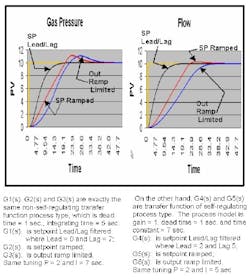
Wherever the ramp is located – either at the controller output or at the setpoint – there will certainly be an overshoot for a non-self-regulating process and a high potential of overshoot for a self-regulating process (higher potential for Lag dominant process model) according to the tuning’s aggressiveness (See Figure 1 below). This is what we see by looking at G2(s), G3(s) and G5(s): all of them are overshot. On the other hand, G1(s), which was step changed through a Lead/Lag filter, not only is overshot, but it reached the new setpoint faster with exactly the same tuning. Consequently, the ramp will postpone the setpoint response and make it overshot. Thus, the first statement that leads people to use ramp, happens to be unjustified for both self-regulating and non-self-regulating process types.
Performances based on a simulation for a self-regulating and non-self-regulating process model. A ramped SP versus a step changed SP going through a Lead/Lag filter has been applied.
WHAT IS THIS Lead/Lag filter? This function is often available as a built-in device in most DCSes and PLCs on the market. It consists of a ratio between 0 and 1 of two time constants. One of them is the numerator and acts as the leader. The leader corresponds to the instantaneous portion of the step change applied to the controller. For instance, if the ratio is 0.7 then 70% of the step is instant or abrupt change and the other 30% is going through a first order filter, which is also called Lag.
The denominator is the lag, which is actually the time constant of a first order filter. Generally, this filter time constant will match the tuning value of the integral action in the controller. This type of mechanism will give you the best of the two worlds: no overshoot during setpoint change and fast load rejection.
Because of this Lead/Lag filter, tuning can be optimized for load disturbances without having any overshoot at all during a setpoint change. Furthermore, the load rejection will remain the fastest it can get during a load disturbance. Without a Lead/Lag filter, most people’s natural tendency is to relax the tuning to avoid overshooting too much on a set point change, or to use a ramp and get an overshoot of different magnitude depending on the tuning’s aggressiveness.
When using a Lead/Lag filter, the excitation signal sent to the PID controller has a sharp break at the beginning, then the rest of the pattern is very smooth. In fact, it has the same shape as a first order response. When using the ramp pattern, there are two abrupt changes: there is one at the beginning and a second one at the end when it reaches the new setpoint. The idea of a Lead/Lag function is to make a steep change at the beginning, when it is far away from the final value, then reduce the speed for the final approach. A two-degree of freedom PID controller (Integral only on SP change) will produce similar results.
The settling time can be improved by a factor of two without overshoot when using a Lead/Lag filter. Settling time is defined as the time that has passed for both the Process Value and Controller Output to reach steady state and remain within the range of a normal process noise.
The settling time is cut by a factor of two when using a Lead/Lag filter, as opposed to using a ramp applied on the set point or using a ramp limiter applied at the controller output where this latter acts as a slew rate limiter.
In addition to lengthening the settling time by 100%, the ramp caused (in this example) an overshoot of 10%. If the aggressiveness of the tuning and the slope of the ramp are reduced to lessen the overshoot as much as possible to the minimum, then the settling time could be increased by a factor as high as four, which is a considerable amount. Consequently, with a ramp, the reduction of the overshoot during a set point change implies a significant increase of the settling time. On the opposite, the Lead/Lag filter does not create overshoot for both types of process, that is to say self-regulating and non-self-regulating.
Respecting Equipment Constraints
For the second solution, which is intended to protect the equipment from being stressed, over-used or broken, there is a more appropriate approach to solve this issue than using a ramp limiter at the PID output. For instance, if the cause of the stress is brought about by a high heat flow rate phenomenon, then another controller could be acting as an override or constraint controller on the temperature differential between the two surfaces or two points. A constraint controller will override the valve through a low-select signal block. Since the stress from the heat is proportional to the heat flow, which is a consequence of the temperature differential between the two points, this constraint controller will take over by just the appropriate amount of output correction and avoid causing stress.
For other applications, a constraint controller could also be based on electrical current, pressure, level, density, etc. Here, instead of switching from a controller to a ramp limiter, the control is switched from one controller to another, which is still a linear device. A PID controller is defined as being a linear piece of equipment unless the output is saturated at either 0% or 100%, or any other external device would limit the controller output. On the other hand, a ramp limiter is a non-linear function block. Mathematically, a linear function is defined as K*y = K*x.
When the ramp limiter takes over the PID and prevents it from moving overly fast, then the previous equation becomes K*y K*x+bias and is not satisfied all the way through 0% to 100% any more. As a matter of fact, whenever a rule-based function-- such as “if X then conclude Y; else conclude Z”-- is being used in a control scheme, a non-linearity is inserted. When a non-linearity is present, the behaviour of the closed-loop becomes harder to predict and is definitely different throughout the full range of the controller’s 0% to 100% output. In fact, this type of rule-based mechanism is most likely suitable when the process is so non-linear that an operator can beat the linear controller (PID) by manipulating the output in manual mode. Alternative types of controllers such as Fuzzy logic and Expert System could then be used to achieve better performance.
Making the Transition from One Operating Point to Another Smoother
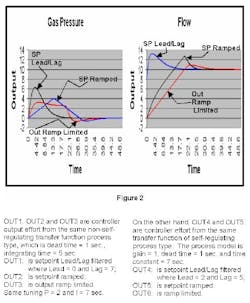
As for the third solution, which aims to make the transition from one operating zone to another production rate smoother, it is somewhat not as smooth as people would expect it to be. As we saw in Figure 1, the ramp creates an overshoot for a non-self-regulating process and likely produces the same on self-regulating process, depending on tuning’s aggressiveness, when looking at the process value (PV). But now, if we look at the output’s behavior (See Figure 2 below), the pattern exhibits sharp breaks (OUT2, OUT3 and OUT5) and all these three involve a ramp device.
WHAT IS SO awful about having a sharp break? Referring to the fundamental of frequency domain according to Fourier theorem, “Any signal can be synthesized by the sum of sinusoids of different frequencies that are multiple integer (harmonics) of the periodic signal to be reproduced.” Moreover, the more sinusoids of high frequency are added, the sharper the synthesized signal will get. For instance, to generate a square wave of 2Hz, all odd multiple integer frequencies (also called harmonics) of the square wave [ (1X2Hz)+(3X2Hz)+(5X2Hz)+(7X2Hz)+(nX2Hz)…] will be added up together and create the 2Hz square wave. Moreover, the higher =the frequencies, the sharper the corner of those square waves get. Therefore, based on Fourier Theory, during a setpoint ramping those two sharp breaks will generate lots of high frequency harmonics (many integer multiple frequencies), which in return will cause the controller to have a higher risk of oscillation. This is why those abrupt changes are so violent.
Why is the ramp effect worse on a non-self-regulating process type than on a self-regulating one? The non-self-regulating is, in other words, an integrating process. The down side of an integrating process type is that it will create more Lag (i.e., an important phase shift). As a matter of fact, an integrating function causes a phase shift of 90 deg. Therefore, in theory, when using two integrators back to back, a 180 deg phase shift takes place since a perfect oscillator is being produced. In practice, a third integrator function may be required to obtain a perfect oscillator. Since a ramp can be mathematically reproduced by the integration of a step, that ramp could represent that third component needed for the oscillation to occur.
When referring to the first three statements, we began by saying that none of them are well served by the use of a ramp function. Moreover, a ramp will insert non-linearity, which is really not suitable in a regulatory control scheme using PID. As stated previously, a PID controller is by definition a linear piece of equipment; as long as this PID controller will be working in a linear environment, its behavior will be predictable. Finally, a ramp will postpone the setpoint response and make it overshoot. So why would we use those ramp functions to turn something linear to non-linear, when there are many other means to achieve the same goal?
Implementation of a Lead/Lag Filter Within an Hour
Depending on the DCS or PLC, the implementation may vary from one minute to one hour. Some DCSes have this feature as a built-in function in the PID controller. In that case, the only task that is left to do is to specify the Lead value. The Lag will inherit the same value as the integral time of the PID controller. In other cases, most DCSes and PLCs will have a Lead/Lag function available and minimum programming will be required to insert the Lead/Lag block in the control scheme. Finally, if nothing exists, we can create programmatically the whole Lead/Lag tool within an hour.
| About the Author |

Leaders relevant to this article:
