By Cecil L. Smith, PE
The traditional use of current loops as inputs to control systems is being replaced by measurement devices and/or input systems that provide the measured value in engineering units. In the era of digital technology, this is indeed appropriate. Unfortunately, the resolution of the digital values is often less than what became the norm for current loop inputs; e.g., a resolution of approximately 1 part in 4000.
Normally such a resolution is far beyond what is required on displays to the process operator, management reports, etc. The value chosen for the resolution is usually based on two factors:
- How many digits after the decimal point do operators really need to see?
- What is the accuracy of the measurement device itself?
This article examines this issue from the perspective of regulatory control; more specifically, the impact of the resolution of the measured value on the performance of the proportional-integral-derivative (PID) controller. Control calculations often need a greater resolution than is required for data presented to humans. Furthermore, the performance of regulatory control actually depends on the repeatability of the measurement device, not its accuracy.
What's the Impact?
The impact of poor resolution on the three modes is as follows:
Proportional mode: Causes the output to change abruptly from one value to another.
Integral or reset mode: Not significantly affected by resolution.
Derivative mode: Causes pulses or 'bumps' to appear in the controller output.
Pressure Control Example
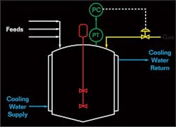
This example in Figure 1 is a simple pressure control application in a reactor. One of the reactants is supplied via a gas. This material dissolves in the liquid within the reactor, from which it reacts with one or more components of the feeds. The objective of the pressure control loop is to maintain a constant pressure within the reactor by supplying gas to replenish the gas being consumed by the reaction.
As part of a general instrumentation and controls upgrade, an electronic analog controller was replaced by a controller implemented in a digital system. The measured variable for the pressure is still provided via a current loop. However, the input module within the digital system converted the current loop input into a digital value in engineering units. The result is a value in engineering units but expressed as an integer variable with the decimal point at an understood location.
The measurement range for the reactor pressure was 0 to 10 psig. Expressing the pressure to 0.1 psig was deemed satisfactory for operator displays. The input module was configured to report the pressure to 0.1 psig, which meant that an integer value of 74 is understood to be 7.4 psig.
There are definitely merits in performing the engineering units conversion in the input module. One is that the hand-held monitor used by the instrument technicians would display the value in engineering units. The value displayed on the hand-held monitor is exactly the same as the value of the graphic displays. In most cases, the instrument technicians are able to diagnose I/O problems without any knowledge of the digital control system.
All seemed quite satisfactory until the pressure loop was commissioned. The digital system exhibited a characteristic that was never observed with the conventional controller. Specifically, the output to the pressure control valve did not change in a smooth manner. Instead, the output to the valve would change abruptly from one value to another.
This is one consequence of poor resolution. With the input module configured in this manner, an input value of 0 means 0.0 psig, and an input value of 100 means 10.0 psig. This input has a resolution of 1 part in 100. The accuracy of modern pressure transmitters is far superior to this, and their repeatability is even better.
Why does this lead to abrupt changes in the controller output? Let's examine the proportional mode calculations. The proportional mode equation is actually a proportional-plus-bias equation that can be expressed as follows:
M = KcE + MR
where M = Controller output, %
Kc= Controller gain, %/%
E = Control error, %
= PV – SP for a direct acting controller
= SP – PV for a reverse acting controller
Mc= Controller output bias, %
PV = Process variable or measured variable, %
SP = Set point or target, %
This is the position form of the proportional mode equation. The impact of resolution is more evident when the equation is expressed in the incremental or velocity form:
∆M = Kc∆E
where ∆M = Change in controller output, %
∆E = Change in control error, %
The product chemists specified the pressure for reacting conditions; changes were not allowed. Therefore, changes in the control error can only be the result of changes in the PV.
With a resolution of 1 part in 100, the smallest change provided by the input module was 1% of the span. The smallest change in the proportional mode output is the controller gain Kc times the smallest change in the control error. With the controller gain set at 5%/%, the smallest change in the output of the proportional mode equation is (1%) x (5%/%) = 5%. Such changes appear directly in the controller output.
There are two options to achieve smaller changes in the output of the proportional mode equation:
- Reduce the controller gain Kc The controller gain is a tuning parameter whose value should reflect the characteristicsof the process. For a responsive pressure loop, a value of 5%/% for the controller gain is not unreasonable. Reducing the controller gain also sacrifices loop performance, with the unfortunate result being that the performance of the digital system is inferior to that of the conventional controller.
- Improve the resolution of the measured value. In this application, the input value could easily be changed to provide the pressure to 0.01 psig. Now the range of the input value is 0 (or 0.00 psig) to 1000 (or 10.00 psig), which provides a resolution of 1 part in 1000. The smallest change in the proportional mode output is now 0.5%, which is closer to what most valves are actually capable of implementing.
The Unpopular Third Option
Actually there is a third option, but one that is not popular with control engineers. One can apply smoothing to the measured value. The controller output no longer changes abruptly, but in reality the smoothing only masks the fact that the output is changing in 5% increments. By the time enough smoothing is added to completely obscure this behavior, the performance of the loop will suffer. This is another case where smoothing only obscures the problem. One should fix the problem, not try to hide it.
Derivative Mode Calculations
Digital values are an approximation of an analog value. The error in the approximation depends on the resolution of the digital value, which is commonly thought of as either the number of significant digits used to express the digital value, or the number of digits provided after the decimal point, etc. In mathematical circles, the terms 'finite arithmetic' and 'quantization error' apply when the resolution is limited (as it must be in any practical application).
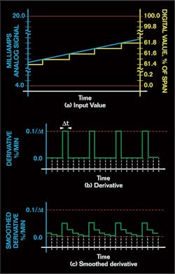
Figure 2:By the time enough smoothing is added to completely obscure this behavior, the performance of the loop will suffer.
llustrates a situation where an analog value is changing at a steady but slow rate. In the context of derivative, slow rates of change are the norm. Derivative action is most frequently applied to temperature loops, which in process plants usually respond very slowly.
The digital value, expressed as % of span in Figure 2, is represented to one digit after the decimal point. But whereas the analog value changes at a smooth and steady rate, the digital value changes by increments. The digital value is constant for some period of time, and then changes abruptly by the amount imposed by the resolution. In Figure 2, this change is 0.1% of span.
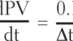
Let's examine the impact of this on calculating the derivative or rate of change. The simplest approximation to the derivative is the finite difference approximation:
where PV = Measured value, % of span
t = Time, minutes
∆t = Loop execution interval, minutes
n = Sampling instant = t / ∆t
PVn= Value of PV at sampling instant n or PV at time t = n ∆t
When the PV is changing very slowly as in Figure 2, the digital value does not change on every sampling interval. That is, for most sampling intervals, PVn = PVn–1, which means that the derivative is zero. But on certain sampling intervals, the PV changes by 0.1% (with the resolution as illustrated in Figure 2). For this sampling instant, the derivative is
Consequently, the derivative is the sequence of pulses illustrated in Figure 2. On most sampling instants, the derivative is zero. But on certain sampling instants, the derivative is a pulse of height 0.1/∆t and duration ∆t.
This is one case where short sampling intervals can be counterproductive. Temperature loops constitute a high percentage of the applications of the derivative mode. Temperature loops in the process industries are generally slow, and for most, a sampling interval of 20 or 30 seconds is entirely adequate. The use of a longer sampling interval has two advantages:
- The longer the sampling interval, the more likely that the temperature has changed sufficiently to be reflected in the digital value.
- For longer sampling intervals, the pulse has a smaller amplitude and a longer duration.
In most digital systems, the implementation of the derivative mode includes some smoothing or filtering. The relative parameter is one of the following:
- Derivative mode smoothing factor α.
- Derivative gain limit.
These two parameters are the reciprocal of each other. That is, a derivative gain limit of 10 corresponds to a derivative mode smoothing factor α of 0.1. In most digital systems, the recommended value for α is 0.1. A few systems permit the derivative mode smoothing factor (or the derivative gain limit) to be adjusted; most do not. Even when the system permits the value to be adjusted, most just use the default value (typically a derivative mode smoothing factor of 0.1).
How this smoothing factor is implemented depends somewhat on how the derivative mode is implemented. However, the net result is basically the same. For the digital systems that follow the conventional controller approach of implementing the derivative via a lead-lag element, the PID calculations can be expressed in the following manner:
Apply the proportional-derivative calculations (but with a gain of 1.0) to the measured variable PV to obtain a projected or predicted value of the PV one derivative time in the future. Basically, this assumes that the current rate of change of the measured variable will persist for one derivative time into the future. The applicable equation is as follows:- Use the projected control error Ê in both the proportional and integral mode equations. This results in what is called the series, interacting, or non-ideal form of the PID control equation.
- Use the projected control error Ê in the proportional mode equation, but use the control error E in the integral mode equations. This results in what is called the parallel, non-interacting, or ideal form of the PID control equation.
The above implementation applies the derivative only to the measured variable. With minor modifications to the above equations, the derivative can be based on the control error E.
There are two options for incorporating smoothing into this implementation of the PID control equation:
- Apply smoothing to the derivative PV'.
- Apply smoothing to the projected value PV^ for the PV. This is equivalent to implementing the derivative mode via a lead-lag element.
The result is substantially the same, so only applying smoothing to PV^ will be illustrated. The smoothing assumes the form of the customary lag filter, and can be represented as follows:
where PV¯ = Smoothed value of the projected value PV^ for the PV, %
The control error is then the difference between the set point and the smoothed value PV¯ for the projected PV.
The result of this is the smoothed derivative illustrated in Figure 2. Generally, this attenuates the height of the pulse and imparts a decaying exponential to the trailing edge of the pulse. The larger the value of the derivative mode smoothing factor, the more the pulse is attenuated, and the slower the decay on the trailing edge of the pulse.
By increasing the derivative mode smoothing factor α, the output of the derivative mode is 'leveled.' However, there is always a downside to smoothing. In the implementation presented above, the maximum value of the derivative mode smoothing factor α is 1.0, or a derivative gain limit of 1.0. With α = 1.0 in the implementation presented above, the smoothing exactly cancels the effect of the proportional-derivative calculation, which is as if the derivative mode is removed entirely.
Basically, the notion of derivative is to 'anticipate' the process, which is reflected in the older term 'pre-act' that was applied to derivative. One component of the control action is based on the rate of change of the measured variable. The incorporation of smoothing into the derivative mode provides a lag on this rate of change. Especially when the sampling time ∆t is short, some smoothing is necessary. But excessive smoothing reduces the effectiveness of the derivative mode.
In most applications, users are either stuck with the value of α that is set by the supplier or simply accept the supplier's default value for α. Even if one can adjust the value of α, this proves to be ineffective at compensating for the consequences of a poor resolution on the measured variable. The result of a poor resolution on the measured variable is one of the following:
- For the usual derivative mode smoothing factor of 0.1, 'bumps' will be observed in the output of the controller. The measured variable changes by one quantization unit, giving a 'bump' in the derivative mode output that appears in the controller output.
- Increasing the derivative mode smoothing factor will reduce the magnitude of the 'bump' in the controller output, but by the time enough smoothing has been added to significantly reduce the 'fbump,' the effectiveness of the derivative mode has been reduced to the point that offers little improvement to loop performance.
Tune in next month for part two of this essay, and send your questions to Ask the Expert.
Cecil L. Smith, PhD, PE's consulting practice is devoted exclusively to industrial automation, encompassing both batch and continuous processes. He also teaches continuing education courses on various aspects of process control. His approach to process control is reflected in these courses and in the computer based training (CBT) package that he has developed on process control.

Leaders relevant to this article:


