Note: The three questions below are similar, so we are answering them together. The goal in each case is to achieve reliable and accurate level measurement in hard-to-handle, corrosive and boiling applications.
[javascriptSnippet]
Q: We have a large tank in which sodium hydroxide is mixed into water and the high pH (>13.5) caustic mixture is heated to 200 °F and continuously agitated and recirculated. (It goes to another tank where it flows over extrusion dies, and then back to the main tank.)Evaporation, other losses and the attendant addition of makeup water and NaOH make it necessary to know the level in the tank. But the fluid in the tank is a hot, dirty, frothy, corrosive nightmare. It is hard to measure level in there, and we have destroyed several types of sensors.
One suggestion is to use pressure sensors at the bottom of the tank to determine level. Is that a good way to measure level in a tank?
William Love
Kredit Automation & Controls
Level Detection of Several Fluid Types
Level detection of sticky, viscous, hard-to-handle, boiling, foaming or corrosive fluids.
Our site manufactures PVC additives. One of our core materials is high-melt paraffin wax, which makes measuring tank levels difficult. We have tried various methods of measuring tank levels (radar, infrared, etc.), but all have been inadequate. Floats or hydrostatic systems get fouled due to heat or wax buildup. Currently we take the measurement manually, but we want to automate the process. Key characteristics for us are 1) The material cannot be touched because it sticks to everything; 2) It must withstand 300 ºF and moderate agitation.Q:
Any suggestions? We’ve heard of nuclear measurement but haven’t found any documentation.
Douglas Dieselberg
Honeywell International
[email protected]
Q: Recently in Control you had an article about drum level median select logic. This got my attention because I’m seeking this information to change our logic (we have a Bailey inf-90) from manual transmitter select to median select.
First you have “less than” blocks with staggered inputs going to a “greater than” block. What is the difference between using “less than” and “greater than” at transmitter inputs?
If a transmitter fails or loop opens, will that drum level be maintained? Is this possible?
Also you mentioned alarms such that the low would be from the lowest, and the high would be from the highest transmitter at any given time. Is this using the same logic as above?
Daniel Sanchez
Colmac Energy
[email protected]
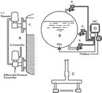
A: The most frequently used level measurement device on slurry and sludge services is the extended-diaphragm differential pressure transmitter (Figure 1a). The diaphragm extension eliminates the dead-ended cavity in the nozzle where materials accumulate and brings the sensing diaphragm flush with the inside surface of the tank. A Teflon coating on the sensing diaphragm or using corrosion-resistant materials can further minimize material buildup.
One of the best methods of keeping the low-pressure side of the d/p cell clean is to also insert an extended-diaphragm device in the upper nozzle. This can be a pressure repeater, which is capable of repeating both vacuums and pressures if they are within the range of the available vacuum, and plant or instrument air supply pressures. Outside of these pressures, extended-diaphragm chemical seals can be used if they are properly compensated for ambient temperature variations and sun exposure.
D/p measurement detects the mass and not the volume of the tank contents. Therefore, if the density varies, d/p detection does not detect level. When the tank contents are boiling, both the boil rate and the vapor pressure in the vessel will affect the volume percentage taken up by the bubbles. As they vary, bubbles will swell or collapse, and the same amount of fluid will take up different volumes. Therefore, if the level (and not the mass) is to be detected, d/p sensors require density compensation, which can be done with a second d/p located so that both the high and low pressure sensors are in the liquid (Figure 1b). A second choice is to use separate point sensors (level switches) located in the vapor space and provide safety overrides when the level is too high or too low. A third option is to use external devices, such as radiation gauges.
In case of foaming, one must detect both the liquid-foam interface and the foam level. Radiation sensors can detect the liquid-foam interface, and time domain reflectometry (TDR) transmitters or conductance and RF switches can detect the foam level if it is conductive. In the case of heavier foams, vibrating or tuning fork switches and beta radiation gauges are possibilities; in some cases, optical or thermal switches have also been successful. When the process fluid is very sticky or corrosive, beam breaker switches (Figure 1c) can detect the high level.
Béla Lipták
A: Re: Median Selection
There are several ways to build a median selector:
- It can be done on the 4-20 mA outputs from the transmitters using Zener diodes, as described in my US Patent 3,418,486.
- It can be done using selector blocks: Feed all three signals into one hi-sel block, one lo-sel block and a summer; then connect both selector outputs to negative inputs of the same summer. The highest and lowest are then subtracted from the sum, leaving the median as an output.
- Logic can also be used:
If A > B and B > C, then X = B.
Else if A > C and C > B, then X = C.
Else X = A.
A single failure in either direction will not disrupt control. This is equivalent to “two-out-of-three logic” used in nuclear power plants, but simultaneous failures in both directions are also accommodated. Median selection also provides noise filtering without an associated lag, since positive and negative spikes are both rejected by the selector.
Greg Shinskey
Process Control Consultant
A: Re:Molten wax level
Try differential pressure, using diaphragm sensors flush to the tank wall. The high-pressure diaphragm is fully submerged, sensing the total head above itself. The low-pressure diaphragm in the wall of the tank well above the fluid can be located near a heat source to minimize build-up if need be. It senses the pressure above the wax. The difference in pressure, corrected for density, represents the level above the high pressure diaphragm.
Otto Muller-Girard, PE,
FISA
A: Re:Level of molten wax
Nuclear attenuation is certainly a possibility for your application. Check such manufacturers as Vega, Omega, Berthold and Able (UK). You may be surprised at the cost of ownership.
If you can incorporate load cells into the vessel mounting, it is a less expensive method. This is indirect level by measuring mass, but assuming you know the density and geometry, level can be deduced.
Gary G. Sanders
A: Re: Wax level detection
A RF frequency admittance (capacitance) probe might work. It “sees” through coatings. Inquire with Drexelbrook or Endress-Hauser.
Stephan Gaertner, PE,
Chevron, Richmond, California
A: Causic Level
Dear Bela, here's an answer from our level experts:
There will always be issues with pressure transmitters due to their compatability with caustic soda. A ceramic (99,9% pure ceramic) transmitter sensor performs much better, but there will be trouble in finding a suitable O-ring!
The best experience with caustic solutions has been made using a non-contact radar transmitter with PTFE antenna. However, its success depends upon:
- how turbulent the surface is
- how big the vessel is (diameter)
- how many obstacles are mounted inside the vessel
If the worse comes to the worse, a radiometrical (gamma) measurement is always possible.
Regards,
Peter
Manager Marketing Communication
Endress+Hauser Process Solutions AG
A: Caustic Level
Several manufacturers offer hydrostatic tank gages based on multiple pressure measurements. The output can be in terms of level, volume, or mass as desired, as density is also determined. As a start, go to Foxboro.com and look for hydrostatic tank gages.
Greg Shinskey
Process Control Consultant
A: Caustic Level
Bela:
If I understand the situation, unfornately this application has variable density of the NaOH solution. Pressure transducers will only measure head pressure which will vary both with level and density.
Regards,
Gary G. Sanders
Director of Engineering
TV&C - Prophetstown
Penberthy and Yarway Products
A: Caustic Level
Use a nitrogen bubbler technique. Place the pressure transducer at the top of the tank and a tube extending from the transducer to the bottom of the tank. Now add a slight flow of clean compatible gas to the tube via the use of at T fitting. Adjust the gas flow to allow a slight flow when the tank is full. As the level drops the back pressure will decrease with level. A simpler method is to not add the gas flow and to just depend upon the back pressure. While using a tube without flow generally works, the gas flow helps to keep the measurement pipe clear of deposits. The gas flow will drastically reduce the corrosion of the transducer, but you still need to make sure that the transducer and all materials are compatible with the liquid being measured.
Bruce Land
Johns Hopkins University
Applied Physics Laboratory
A: Caustic Level
The use of pressure sensing at the bottom of the vessel is an effective way to measure as long as the intrusive components into the vessel (seals and gaskets) used have material compatibility with the process and the various specific gravities of the process are not varying which would create measurement errors.
Not knowing the physical dimensions of the vessel and the desired measurement range in question, a non intrusive measurement might be possible with a nuclear continuous detector and an external mounted source holder with a source. It avoids the process issues stated in the email and generally can be located to miss the agitator shaft (assuming a slow agitation rate with no vortex formation).
The solution is higher priced and requires a license but will result in more of a trouble free application.
Jack Rodgers
VP of Nuclear Business
[email protected]

Leaders relevant to this article:


