Working with IS and non-Signals on the Plant Floor
Have you ever been presented with a challenge like one of these? You need to transmit a signal through from one safe area (plant furnace or analyzer shelter) to another (control room) through a hazardous area; add a non-IS (Intrinsically Safe) signal to an IS multi-core cable; or simply make a signal IS “in the field” where a “good ground” is not available?
This article will describe the above situations in a bit more detail to help you identify similar scenarios at your facility and then show how galvanic isolators are a valid option to provide solution to all the above problems.
Figure 1 illustrates a typical plant situation with different area classifications, such as are found when going from one “safe area” of a facility to another. This example is typical in that a signal from, say, a flue stack analyzer mounted on a furnace (an unclassified area because of the open flames in the burner) is connected to a junction box in the process unit (could be a Class 1 Division 1 Group B hydrogen facility) that then terminates in the DCS rack room.
Such situations happen all the time, for example, when a non-IS signal needs to be made into an IS signal, but you only have IS multi-pair home-run cables from the field to the rack room. In another likely scenario, all the signals originating from the Class 1 Division 1 or Division 2 area (especially if it is Gas Group B) are made intrinsically safe to provide the highest level of protection from an explosion. Running a new non-IS cable to capture the few signals that are not IS at an installed cost of approximately $1000/foot quickly becomes prohibitively expensive.
Another form of “safe area” is the inside of an explosion-proof enclosure. As long as the rules for explosion-proof enclosures either enclose the equipment all in the same box or pour seals as appropriate between enclosures, the enclosure can be considered a “safe” or unclassified area as far as the source of signal is concerned because an explosion-proof enclosure, though not necessarily a “safe area” in its interior―provided the enclosure is maintained and properly closed with all bolts tightened―will contain the explosion inside and not propagate to the surrounding environment. The “spark” or explosion will not migrate down the wire either. Cooper Crouse Hinds has two videos on its website that demonstrate the importance of maintaining the integrity of an explosion-proof enclosure. The first at www.crouse-hinds.com/smart/Videos/flame_prop.mpg demonstrates how a flame can be transmitted and the impact of an explosion amplified through poor practices, while the second at www.crouse-hinds.com/smart/Videos/Haz%20Loc%20Equip.wmv shows the importance of properly installing and maintaining your explosion-proof enclosures.
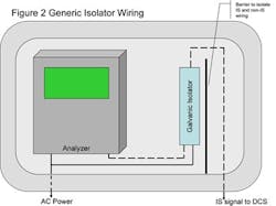
Figure 2 shows how an explosion-proof enclosure containing a high-energy circuit, such as a process analyzer without IS outputs, might be wired to make a non-IS signal IS for transmission through the hazardous area or as part of an IS signal cable. Incidentally, if you have the reverse situation―an IS signal output from your transmitter and only non-IS cables back to your control room―the same solution can be applied, except with the hazardous area (IS) signal being connected to the instrument end of the isolator rather than to the DCS home-run cable.
How does it work?
In simple terms, how does a galvanic isolator as shown in these figures work and how it is connected to the safe and hazardous area devices?
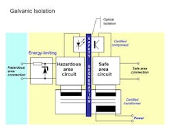
The most critical component in a galvanic isolator is, as the name implies, the safety segregation of the two sets of circuitry. In the case of the power supply, this is done through the use of a certified transformer. Like most transformers, this one uses Faraday’s Law to transfer electrical energy across a suitable gap from one energy level to another: For example, as shown in the above example, a 120 VAC or 220 VAC input to a DC output for both the safe and hazardous signals. The “safe area circuit” requires power to drive the signal into the DCS, while the “hazardous area circuit” going to the IS cable also requires power to drive the loop. The other isolation for the 4-20 mA instrument signal is typically done via optical isolators. Light is shone over a gap and the receptor on the safe side of this isolation converts the amount of light it receives to a signal proportional to the full range of the input scale regardless, whether this scale is analog or discrete. The final critical circuitry in an isolator is the energy-limiting component on the signal to the hazardous area. This circuitry typical consists of shunt diode(s) and a fuse to prevent any energy excursions above the safe limit from entering the signal cable going to the hazardous area where it could potentially lead to an explosion.
Because IS works by limiting the energy on the wire to a level below where it could cause an explosion in the presence of a fault, such as a short circuit, IS signals to the field are typically constrained to approximately 16.5 volts on the output terminals of the isolator going into the hazardous area. This, of course, could in some cases place a limit on the maximum length of cable from the isolator or barrier to the field device. Yes, Dorothy, Ohm’s law still applies, so voltage will drop as the length of the wire (resistance) increases. (Current does not change, as that will be the approximately 14 mA required to drive the analog transmitter in the field.)
You can also use isolators that are repeaters or signal amplifiers, however as you can see from the above example and diagram, they will require a reliable power supply in the field to insure uninterrupted signal communications, so in this case the “weakest link” is likely to be the field power supply. However, if this is your only option, the risk must be managed in other ways or alternate technologies besides twisted copper pair be used.
The electrical code specifies that IS and non-IS cables must be separated with barriers and minimum spacing. Most installations in which mixed signal types are in the same environment have clear marking to differentiate the IS and non-IS areas within the enclosure. In addition many installations specify a blue mylar sheath on IS cables so technicians working on a cable can immediately see the difference. Designers of barriers and isolators also have spacing limitations that apply to the layout of terminals and connections of the barriers and galvanic Isolators as well.
Key benefits of isolators versus barriers, which are typically installed in the rack room with a good system ground connection the most commonly used option for IS installations, include:
- Fairly complex, statistically lower mean time between failures (MTBF) than barriers – Because the isolator has more components than a barrier, it has a lower MTBF than the barrier option. However the MTBF for barriers and isolators is
- Flexibility in bonding practice – Circuitry is isolated so the grounding requirements for an Isolator are more lenient than the
- Active devices; power and heat – Isolators have electronics, such as transformers and isolators, as part of their design, all of which require power to operate, and as a result generate heat that must be dissipated.
- “Application-specific” – an isolator is defined in terms of function and therefore requires different circuitry and design for analog input, analog output, discrete or frequency signal.
- Wide power supply tolerance – units are available with a range of external power supplies, including DC and a number of AC sources.
On the other hand, isolators are generally more expensive than barriers in part because they have more components.
Intrinsic safety is not the most commonly used explosion prevention technique in North America, however if and when it is required for any of the reasons identified above, or others that may be particular to your plant, it is a globally recognized technique that allows live working of your process at minimal risk or additional expense, while providing complete flexibility on the type of signal cable installed between your field junction boxes and rack room. IS may not be suitable for every hazardous area application, however, it is a viable alternative and flexible enough to be used in a wide range of applications.
About the Author:
Ian Verhappen is an ISA Fellow, Certified Automation Professional and a recognized authority on industrial communications technologies with 25+ years experience in the hydrocarbon industry. Ian can be reached at [email protected].

Leaders relevant to this article:


