"Ask the Experts" is moderated by Béla Lipták, process control consultant and editor of the Instrument Engineer's Handbook (IEH). He is now recruiting new contributors for the 5th edition. If you are qualified to contribute to this volume, or if you are qualified to answer questions in this column or want to ask a question, write to [email protected].
Q:
Using faulty measurements can fool even the best control system. To avoid costly mistakes it is necessary to understand the measurement technique and its limitations. This guide focuses on differential pressure level measurement and three different techniques used to calibrate pressure level transmitters.
Drift:
ANSI/ISA-S51.1-1979 (R1993). [ISARP67.04.01-2000.ISA-RP67.04.02-2000]. — An undesired change in output over a period of time, where the change is unrelated to the input, environment or load.
[ANSI/ISA-75.05.01-2000] 3. — An undesired change in the output/input relationship over time.
[ISA-37.1-1975 (1992)] — An undesired change in output over time that is not a function of the measurand. Drift is usually expressed as the change in output over a specified time with fixed input and operation conditions. It is usually used in the context of analog transducers, analyzers, etc.
Stability:
[ISA-37.1-1975 (R1982)] — The ability of a transducer to retain its performance characteristics for a relatively long period of time. Unless otherwise stated, stability is the ability of a transducer to reproduce output readings obtained during its original calibration, at room conditions, for a specified period of time. It is then typically expressed as being "within X percent of full scale output for a period of Y months.
[SA-RP55.1-1975(R1983)]— In data processing, a measure of the ability of a device to maintain constant volumes for one or more parameters that describe its operation. Freedom from undesirable deviation. A measure of the controllability of a process.
In our work, these two terms are used quite interchangeably. When we are calibrating an instrument, and it has an offset, we say it has drifted. Similarly most test equipment, such as dry bath calibrators, has stability (both long-term and short-term) in its specifications. As an aside, stability is also used to define a process controller that brings the process to new setpoint after a disturbance. But, at that time, we know that we are dealing with a process.
I would like to know how we differentiate between these two characteristics? How do we measure them separately when evaluating a sensor or another instrument? Similarly, in order to correctly determine and publish offset and bias of the various instruments, how should we better understand what they are?
Yusaf Muti
[email protected]
A: The first 150 pages of Volume 1 of the Instrument Engineers' Handbook deals with such general topics. In this age of advertisements that show attractive people and places instead of guaranteed and clearly defined performance data, it is hard to know how good a sensor is. Some manufacturers do not even test all their sensors, and their specifications do not even state how the published numbers have been arrived at.
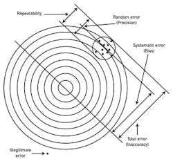
Figure 1. Terms describing the error (inaccuracy) of a sensor
For this reason, it would be useful if ISA recommended the testing methods and also recommended that the performance found be printed on all instrument specifications, no matter where the device was produced around the world. For example, ISA could recommend that all drift specifications state if the sensors were individually tested (or only sampled), and state that the drift was measured, say, "for a period of X hours and was found to be Y% of output span."Also. as I have illustrated in Figure 1, the total error (inaccuracy) of a measurement is the sum of its systematic and its random errors.
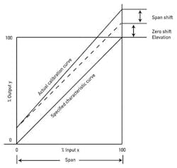
The error caused by drift (some also call it shift), illustrated in Figure 2, is the difference between the specified and the actual performance of a sensor over a time period. The total drift error is the sum of two error components: the zero and the span shifts over some time period. When running a test to determine these values, one has to be careful to evaluate the whole system, not only the transmitter electronics. Let me illustrate that point by a recent experience:
Therefore, the evaluation of the drift should also be based on testing the primary and the secondary together using the actual measurement signal and not a simulated one.
Stability is a more general term, as it can include not only drift (which is a function of the passage of time), but also the environmental effects (pressure, temperature, humidity, vibration), process effects (coating, corrosion, aging) and other factors, such as cycling, hysteresis, linearity, noise, etc.
Offset (some also call it droop) is a term used in connection with proportional-only controllers because such devices (thermostats, pressure regulators, etc.) start making a correction only after an error has already developed. The amount of offset rises as the gain of the controller drops (proportional band increases).
Bias occurs when a constant amount is added to or subtracted from a signal. For example, zero shift can bias the output of a sensor. A positive bias of a sensor output results in over- reporting and a negative bias in underreporting the variable measured.
Béla Lipták
[email protected]
Q: I read your article on steam quality measurement with great interest. I am working in a thermal project pilot plant and would like to measure the steam quality at the injection well where the line size is 3 ins. Can you give me some information on "throttling calorimeters"? Also please recommend a steam quality measurement device that is not cumbersome to measure SQ in the 3-in. line.
Vijay Ramlal
[email protected]
A: Standard technique in large power plants in the United States to assure steam quality on super heated steam is to measure sodium ion concentration, usually in ppb in two or more locations. Particular attention should be paid to obtain representative samples before and after the mud flow cycle. Several companies offer products, but sample conditioning is difficult. After several manufacturers' trial application, I found one English company's product to be easy to maintain and reliable. You can write to me directly if you need more information.
Ram.G.Ramachandran
[email protected]

Leaders relevant to this article:


