By Walt Boyes, Editor in Chief
In the past few years, the proliferation of field devices and the proliferation of standards and nomenclature for explosion safety globally have produced a large and wonderful kettle of alphabet soup. Ex, ATEX, Class I, NFPA, explosion-proof. It's amazing that anyone can follow it all.
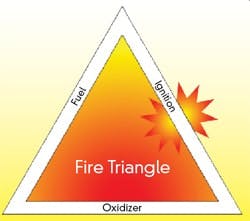
Figure 1. Removing one side of the triangle prevents the explosion.
We are all familiar with the "fire triangle." In Figure 1, we see another version. In this version, the three sides of the triangle are fuel, ignition and oxidizer. To prevent an explosion in or caused by a field device, one or more of the triangle's sides must be absent.There are basically three kinds of explosion safety systems. The first is explosion containment. That means we build a big heavy box around the device that is robust enough to contain any likely explosion within the box. That's the origin of the term "explosion-proof."
The second is the "purge and pressurization" method. This is also called the segregation principle. This method relies on moving a sufficient amount of air, nitrogen or other inert gas through the enclosure quickly enough to be able to remove or dilute the concentration of explosive-potential gases so they don't concentrate enough to explode.
The third is to reduce the potential energy in the device, so there is not enough power available to cause ignition of the fuel/air mixture inside. This, really, is explosion prevention.
It is this last system that we're going to take a "back to the basics" look at here.
Hazardous Area Classifications
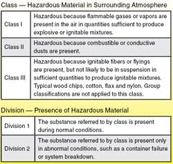
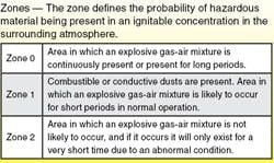
There are significant differences between systems of hazardous area classifications. (See the table 1 and table 2 for an outline of the two systems.)
Source: http://www.engineeringtoolbox.com/hazardous-areas-classification-d_345.html
In the United States, the class and division system is used.Class I and Class II hazardous areas are divided into subgroups according to the type of gases or vapors that are often present there. Class III areas aren't subdivided. The European classification system is based on zones. U.S. Division 1 is roughly equivalent to Zone 0—the case of constant risk, or Zone 1 if the risk is occasional. Division 2 is roughly equivalent to Zone 2, where the risk occurs only in the case of an abnormal situation or fault.In the European system, devices are labeled by codes such as Ex p (pressurization) or Ex i (intrinsic safety) or Ex d (flameproof) based on their method of protection.
What Intrinsic Safety Is, and What It Isn't
The concept of making a device intrinsically safe (IS) is based on the idea that the best way to protect the device is to prevent the source of ignition. In an intrinsically safe device, the electrical energy is kept below the minimum ignition energy (MIE) required for each hazardous area. This is done by limiting current, voltage, power and temperature. This means that IS is limited to devices whose circuits have relatively low levels of power. What this does is prevent sparks or thermal effects that could lead to the ignition of a potentially explosive atmosphere from occurring.
Source: http://www.engineeringtoolbox.com/hazardous-areas-classification-d_395.html
You can connect and disconnect intrinsically safe circuits, even when live, since IS guarantees that they will be safe even in the event of a short circuit.In most of the world, intrinsic safety has replaced other protection schemes because it provides a level of operational freedom that is not matched by other schemes. The biggest drawback of IS as a protection scheme is that it is limited to low-power devices.
Bacically, the concept of intrinsic safety is to use lower-power field devices and connect them through a system of barriers (either using zener diodes or opto- or galvanic isolation), so that the energy available is less than the MIE.
No field device is intrinsically safe by itself. The entire system of wiring to which it is attached must be considered and made safe. This required a tiresome round of re-engineering each installation until the concept of "Entity" appeared. Under this concept, field devices and barriers are certified individually, and can be interconnected fairly easily Just match the parameters for voltage, current and capacitance, and make sure that the device and its barrier are installed in approved fashion.
Intrinsic Safety for Analog Devices
Making analog field devices intrinsically safe and using them in IS applications is pretty simple, as shown in Figure 2. You start with a low-power device, and with the emergence of digital field devices, most transmitters qualify. You install it with a barrier matched to the Entity parameters in the input and/or output wiring, and you're golden.
Figure 2. Intrinsic safety is relatively simple.
Intrinsic Safety for HART
With the development of digital devices, and with the ability of analog signals to carry digitally encoded data, such as the HART protocol, intrinsic safety became more difficult. The power to the device must be reduced to provide "headroom" for the HART signal below the shunt voltage of a zener barrier, and the load resistor needs to be at least 230 Ohms. Designing a HART system using isolators requires more planning. Many isolators can't carry the HART signal that is modulated on the 4-20 mA DC signal across the isolation barrier. You have to ensure that the isolator you are using is designed to be HART-compatible.
Intrinsic Safety for Fieldbus
For Foundation Fieldbus and Profibus digital networks, things again get complicated for IS. In fieldbus applications, the devices require more power than can be provided using analog-style intrinsic safety.
In the late 1990s, a German research organization, PTB, created the Fieldbus Intrinsic Safety Concept (FISCO). First developed for Profibus, it was later expanded to include Foundation fieldbus, since these protocols share a common physical layer. FISCO power supplies are located in safe areas and incorporate active current-limiting circuitry that allows more power to be delivered to fieldbus segments located in hazardous environments. Since the fieldbus segment is made intrinsically safe by placing the barrier at the boundary between safe and hazardous area, the trunk is can be worked "live" or "hot."
No matter what kind of field device you are using, intrinsic safety is achievable for you.
Walt Boyes is Control's editor in chief

Leaders relevant to this article:

