Software that Reduces Maintenance of Multivariable Predictive Controllers
Charles and James Cutler
Also Read: Model Predictive Control - Past, Present and Future, Part 1
All MVs are Setpoints
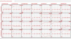
Cutler Technology's Universal Process Identification (UPID) software will be used to demonstrate how the problems with PID configuration and tuning can be reduced to a minimum. A depropanizer model will be used as the process example. The independent manipulated variables in the model are the set points for the feed rate, the top pressure on the column, the tray 5 temperature (5 trays from top), and the heat medium flow to the reboiler. The tray 5 temperature is controlled by manipulating the reflux to the column. The top pressure controller by passes the overhead condensing system and sends the hot vapors directly to the overhead accumulator to increase the pressure. The MPC on the column controls the top temperature and bottom temperature. The differential pressure across the column and the valve position on the pressure controller are the main constraints. These controlled variables are dependent variables in the controller's model. The other dependent variables in the controller model in Display 1 are there to facilitate the rearrangement of the control matrix when it becomes prudent to put one or more of the PID controllers in manual in the MPC model.
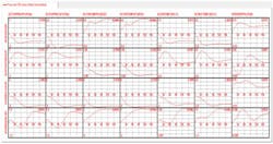
In Display 1, it should be noted that the PV for a specific manipulated variables comes to 1.00, i.e. the PV comes to its setpoint. The response of this PV for the other manipulated variable is zero or comes back to zero at steady state for the other manipulated variables. This response is true because the manipulated variables are independent from one another. The valve positions of the manipulated variables change to make this independence possible.
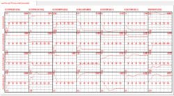
All MVs are Setpoints except Top Pressure which became a VP
In Display 2 the Top Pressure PID controller has been switched to manual in the model. The Top Pressure valve position becomes the manipulated variable. The setpoint for the pressure replaces the valve position as a dependent variable and tracks the pressure PV. During the summer when the cooling water temperature goes up, it becomes desirable to switch the pressure controller to manual, to tell the MPC that it needs to use the other manipulated variables to control the pressure on the column. As can be seen in Display 2, all of the other manipulated variables have a significant effect on the pressure. The MPC controller with the pressure PID controller in manual can completely close the valve on the bypass around the condensers.
Closing the valve permits the maximum cooling for the column.
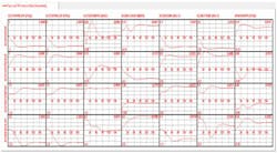
All MVs are Setpoints except Tray 5 Temp which became Top Reflux VP
The Tray 5 Temperature PID controller is switched to manual in Display 3 The PID controller on tray 5 temperature is a cascaded loop that moves the setpoint on the reflux to the column. The MPC controller model in Display 3 has the reflux valve position as one of its independent manipulated variables.
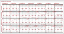
In Display 4, both the temperature PID controller and pressure PID controller are in manual. The MPC model is significantly changed from the original model when all the setpoints were functioning. There are many reasons PID controllers are switched to manual during the course of a run. A run may last a number of years, so every effort should be made to keep MPC on control. A controller may be switched to manual when a valve is sticking so frequently that it is putting cycles into the entire process unit. The process piping may not have adequate by passes to permit the valves to be blocked in and removed for repaired.
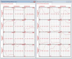
In Display 5, the models for the key constraint CVs are compared for the four set point case and the two set point case. The valve position responses are obviously different from the set point responses. Major differences in the gains also exist for the setpoint versus setpoint responses. When the configurations of the PID controllers within a multivariable controller are changed, it affects the entire controller model.
All MVs are Setpoints except Top Reflux VP and Top Pressure VP
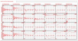
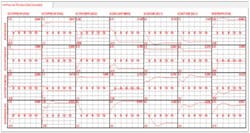
Changes in the process mode of operation may cause one or more controllers to become unstable. The PID controllers must be tuned to gain stability. The new tuning changes the MPC model. In Display 6 the PID controllers have become unstable. The software allows the PIDs controllers in the MPC model to be tuned to match the plants tuning as illustrated in Display 7. The ability to change the PID controller's tuning and configuration in the MPC model to match the current conditions on the process unit can significantly increase the on stream factor, the quality of the MPC control, and the profitability of the controller.
The software is easy to use. The six models that follow, took about 30 minutes to create. The controller has fourteen dependent variables. Seven of the dependent variables were dropped out of the displays to make them readable.
Comparison of controller models with two set points switched to manual
Tuning of Unstable PID: Top Press Kp=40, Ki=3.7 Tray 5 Temp Kp=2, Ki=10
Model after retuning: Top Press Kp=40, Ki=14 Tray 5 Temp Kp=1, Ki=10

Leaders relevant to this article:
