Béla Lipták, PE, control consultant, is editor of the Instrument Engineers' Handbook. He is seeking new co-authors for its upcoming new edition. He can be reached at [email protected].
I am reminded of that comment now, starting this second column on automation of oil platforms. That same kid could probably ask, "What's the big deal? We're just controlling a manometer."
I like this attitude. It's important to clearly understand the very basic nature of a process before getting involved with its many details. Yes, the key to safe operation of an oil well is to maintain the balance between two pressures—just like between the legs of a manometer—by manipulating the hydrostatic head pressure of one leg to balance the oil and gas pressure in the well.
In September's column, I described the crude oil separation process; the measurement and controls required to separate the oil from water, sand and gas; to properly measure the interfaces, the responses to production changes; the needs for maintenance; and the operation of several separators in parallel. Here, I will deal with another phase of this process: the safe automation of the drilling, production and sealing (closing temporarily or permanently) of the well.
Drilling requires attention to pressures
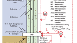
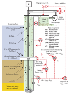
Figure 1: Drilling fluid is pumped down inside the drill pipe, serving the dual purposes of cooling the bit and carrying up the cuttings through the annulus (or annular) between the drill pipe and the bore hole.
The drilling process is illustrated in Figure 1. The drilling mud is circulated as it brings the cuttings to the surface, where they're separated from the mud by a centrifuge or a shale shaker, while the mud is pumped back down to bring up more cuttings. For a detailed listing of the equipment used and for the safety requirements of the operation, please refer to the OSHA documentation at www.osha.gov/SLTC/etools/oilandgas/drilling/drilling.html.As the drilling progresses, a number of casings are installed for support, and a number of blowout preventers (BOP) are added, so if excessive pressure is encountered in the formation (the "manometer" is about to blow out the drilling liquid), the well can be closed.
During this drilling phase, the control goals are to keep the drilling mud pressure (PMUD) at the bottom of the well above the oil/gas pressure (POIL) there, to protect against a blowout if high pressure gas or liquid pockets are encountered. At the same time, PMUD has to be kept below the hydraulic fracturing pressure (PFRACT) at which the drilling fluid would start to penetrate and escape into the wall of the bore hole. Therefore, during drilling one has to keep the flow velocity and pressure of the drilling fluid at the bottom of the borehole high enough to carry up the cuttings, keep the PMUD pressure some 20-25% higher than the oil/gas pressure (POIL) in the formation, and keep the drilling fluid pressure (PMUD), below the fracturing pressure (PFRACT). The control system that will automatically guarantee this is also shown in Figure 1.
Here, the automatic drilling controls maintain the mud pressure above the oil pressure in the formation by adjusting the pump speed, the mud density, and (if the mud tank is pressurized) manipulating the nitrogen pressure in the vapor space of the tank. If, in spite of these controls, the pressure of oil in the formation rises above the mud pressure (POIL > PMUD) and starts to lift the mud (thereby suddenly increasing the returning mud flow), or if excessive amounts of methane are detected in the returning mud, safety interlocks are activated (ΔPS) to close the BOPs. In addition, the automatic safety controls must also be able to detect the development of "kicks" and quickly initiate the response to them. This development can be detected by noting an increase in the flow rate from the well. Kicks can also be detected by the rise in the mud tank level and by the rise in the annulus pressure.
When the formation of a kick is detected, the pressure balance of this "manometer" must be reestablished by: 1) increasing the nitrogen (N2) blanket pressure on the mud tank, which will increase the mud pump suction pressure; 2) increasing the mud pump discharge pressure by increasing the pump speed; or 3) increasing the mud density by increasing the flow of heavy additive. If none of these work, the automatic safety controls must first close the blinding ram BOP that closes the annulus, and if the kick pressure is still rising, must then close the blind shear ram.
Unfortunately, most or none of these automatic controls are provided in the operating systems today, and this causes accidents, like the BP disaster.
Well sealing must pass tests
After drilling the well, it's often temporarily sealed, while production and transportation-related equipment is installed. (BP was in the process of sealing when their accident occurred.) This sealing process is also a "manometer-type," but here the hydrostatic heads that are balancing the oil pressure (POIL) are generated not only by mud, but also by cement and sea water.
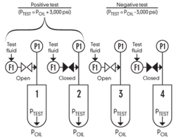
Figure 2: The most critical step in sealing the well is the testing of the integrity of the cement. Pressure differentials of about 3,000 psi in either direction must show no leakage of pressure or flow.
The most critical step in sealing the well is testing the integrity of the cement. This testing involves generating a pressure differential of about 3,000 psi across the cement, and checking if any fluid passes through it in either direction. When the test pressure (PTEST) is above the oil or gas pressure in the formation (POIL), the test is called positive because if the cementing is defective, the liquid will leak from the well. When the test pressure (PTEST) is below the oil or gas pressure in the formation (POIL), the test is called negative because if the well is not properly sealed, leakage will be entering the well (Figure 2).Both positive and negative tests are performed twice, once measuring flow and once measuring pressure. When performing a positive test, PTEST is set at POIL + 3,000 psi, and the first flow test, referred to as "open test," is performed (#1 in Figure 2). During this test, the valve is open, and if there is in-leakage, the flowmeter (FI) reads that flow. Then, the next pressure test, called the "closed test," is performed. In this test, the well is sealed in (the valve is closed as in #2), and if there is out-leakage, the pressure in the well (PI) will drop.
The most important test is the negative one. PTEST is set at 3,000 psi below the oil pressure (POIL), and first the open test is performed (#3 in Figure 2). In this test, the valve is open, and if there is in-leakage, the flowmeter (FI) reads that flow. Then the closed test is performed (#4), in which the valve is closed, and if there is in-leakage, the pressure in the well will rise. In case of the BP accident, both negative tests failed and methane leaked through the cement, but the crew decided to go ahead with the sealing anyway. The consequences we know, and we also know that simple automation could have saved 11 lives and prevented an environmental disaster.
