This column is moderated by Béla Lipták, automation and safety consultant, who is also the editor of the Instrument and Automation Engineers' Handbook (IAEH). If you have automation related questions send them to: [email protected].
Q: I want to know about blowdown percentage we should consider for pressure relief valves in liquid, gas, vapor services. Is there any reference which gives the percentage of blowdown for different services?
Medhi Poor
[email protected]
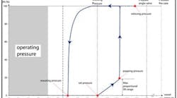
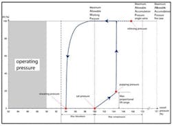
Figure 1: Illustration of the terms used defining the operation of a Series 526 API safety valve provided with adjusting ring. In this design, set pressure is defined as the pressure at which discharge becomes audible. (Courtesy of Leser)
A: Blowdown (blowback) is the difference between the set pressure and the reseating (reclosing) pressure of a relief valve (Figure 1). It is expressed in percentage of the set pressure. Values of blowdown pressures are set by codes (ASME, API, NFPA) and their typical values range from 7% to 10%, while their lower and upper limits are typically adjustable from 2% to 20%. For a detailed discussion see Volume 1 of my handbook, starting on page 973.
Béla Lipták
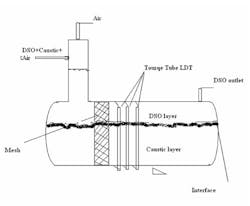
Q: We have a process unit to regenerate caustic in sweetening LPG in a gas plant. During this regeneration process, DSO (Disulfide Oil) is produced. To separate DSO and lean caustic, a horizontal vessel is used (Figure 2). To control the level of this vessel, we are using a displacer torque tube type level transmitter (LDT), but they are always out of service. Would you please explain which type of LDT is suitable?
Figure 2: Given this tank configuration, what is the best way to control the level in the tank?
The specific gravity (SG) of caustic varies between 1.01-1.4 and the SG of DSO is changing between 0.9 -1.1. The heavier phase is always caustic. The LDT is calibrated to indicate the dense layer level (caustic). So we calibrate the LDT according to caustic density but during operation the caustic density varies, and the system is not working properly. So we are planning to purchase a GWR, but I read somewhere that if the dielectric of fluid varies, it will not work properly, and the dielectric of caustic will vary because of the variation in the caustic concentration.
Day Production Supervisor
Siamak Morid
[email protected]
A: This is a very common problem in many separators. So let me comment on the capabilities and limitations of the two techniques you mentioned: displacement and guided wave radar (GWR):
Displacement: Displacers detect the buoyant force. If you calibrate them to read 100% when fully submerged in the bottom layer (it is all in caustic), and the density of that layer varies between 1.01-1.4 SG, the readings will be useless. This is what you are experiencing now. In order to make the measurement meaningful, you also need to measure and compensate for that variable (the density of the caustic). To make the measurement perfect, you would also have to measure the density of the DSO, but since it does not vary much (between 0.9 -1.1 SG), you probably do not need to. After all you do not need high accuracy.
Guided Wave Radar (GWR): Radar, using time domain reflectometry (TDR) has the ability to measure both the upper and lower liquids if the following conditions are met:
- The upper liquid is a low-dielectric medium (ε < 10)
- The lower liquid is a higher-dielectric medium (Δε > 10)
- Both dielectrics are reasonably constant
- The interface is clean and distinct, with no emulsion layer.
If the above conditions were satisfied in your application (which they are not!), the system would work as follows: A small reflection would be generated by the upper DSO layer (low-dielectric) while most of the energy continued down the probe and a larger reflection would be generated by the lower caustic layer (high-dielectric). The key to accuracy is to accurately compensate for the change in pulse propagation velocity while it is traveling through the upper medium.
I would not recommend GWR for your application because your dielectric constants change, and because you have an emulsion layer in which the dielectric changes gradually. For this reason, detectable pulses are not generated from the emulsion layer.
GWR with Float: As caustic is always heavier and the SG of DSO is always lighter, a simple float having a density equaling the maximum density of the light layer is all that is needed, as it will always follow the interface (emulsion), and detecting the position of the float by GWR would give a good enough reading. I do not elaborate on this option as it is explained in detail by my colleague, Hunter Vegas below.
Béla Lipták
[email protected]
A: A displacer level transmitter assumes a consistent SG for both fluids and is usually calibrated to detect the difference of those SG readings in order to determine the level of the interface between the two fluids. However in your case, the SGs of both fluids are varying dramatically, so a consistent calibration and reading is virtually impossible.
I agree that a GWR may not work as well either. It stands a chance if the dielectric properties are reasonably consistent and significantly different. (In other words, if the oil is generally non-conductive, and the caustic is generally very conductive, then it might work ok, but if the conductivity of either fluid can drift dramatically, then your readings will drift all over as well.)
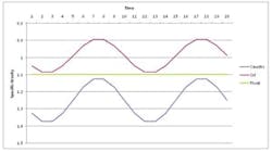
I can think of one possible solution that you might consider. You said the SG of caustic can vary from 1.01 to 1.4, and the SG of the oil can vary from 0.9 to 1.1. Are you certain of this? I am always talking about the process specific gravity at the normal process temperature: Often if you take a sample, and it cools the gravities will get heavier. If the oil gravity can raise higher than the caustic, then the levels would invert, and oil could drop to the bottom. I presume this isn't happening, and the SG of the caustic is at least 1.1. [ital] Assuming that is the case[ital], you could install a float type level transmitter that uses a float with an SG of 1.1. As long as the caustic SG was > 1.1, and the oil SG is <1.1, the float would indicate the interface position even as the SGs of both fluids drifted. (There are several different devices that use a float like this. Some use small reed switches to pick up the float location; others use bounced guided wave radar, etc.)
Figure 3: A float type level transmitter may be the best way to measure level, taking into account the differing specific gravities of the materials in this tank. Credit: Hunter Vegas
In Figure 3 it is assumed that the caustic SG is always > 1.1, and the oil SG is always less than 1.1 Therefore in this case if you had a float having a SG of 1.1, it would [ital] always [ital]float on the caustic and sink in the oil, so it would ride on the interface and provide the indication you need. So you need to determine if there is some SG that will always be greater than the caustic and less than oil, and that is what you set the float to be.
Hunter Vegas
[email protected]
A: You still need to send information on the following:
- It is important to know how much and how fast the specific gravities change so that the optimal setting can be estimated.
- Also provide inlet and outlet flow. It is important since it will define the possibility of the interface layer movements or the generation of the interface or emulsion layer.
- We also need to know the residence time for the emulsion layer to form. This is important, since very turbulent or high flow can cause a non-uniform interface layer or the formation of foam. Both of these can cause errors in the measurement.
- Thickness of the emulsion layer is also needed. This is important since this is what allows a displacer type sensor to measure correctly. If the layer is too thick, has foam or is stratified, then the measurement is difficult or impossible.
- Finally if the emulsion/interface layer has too much foam, is unstable or moves too rapidly, then you may need to look at capacitance or at making the measurement leg larger so that the liquids can separate better. Also adding a level gauge maybe a good idea to provide the ability to check constantly the interface.
Alejandro Varga
[email protected]
