THE TERM “in-situ calibration” means different things to different people. Calibration is a process by which the operation of an instrument is checked against a standard that is known to measure the desired parameter with a high degree of accuracy. A large amount of effort is expended to ensure that the standard achieves and maintains its accuracy. The extent of this effort may not be obvious to its user because off-the-shelf calibrators are engineered to be easy to use and maintain. In contrast, custom calibrators and calibrators manufactured in low volumes tend to require the user to pay more attention to detail.
Recently, especially in the process industries, some new product introductions have raised doubt about what in-situ calibration for flowmeters actually is, and whether it can be duplicated with simulators and calibrators with expanded diagnostics.
Flowmeters are functionally comprised of the flowmeter primary and the flowmeter secondary. The primary is physically involved with the fluid. The secondary, commonly called the transmitter, processes the signal(s) produced by the primary. Examples of primary/secondary pairs are given in Table 1.
TABLE 1: PRIMARY AND SECONDARY FLOW MEASUREMENTS
| Primary | Secondary |
| Orifice Plate | Differential Pressure Transmitter |
| Magnetic Coil/Electrode Assembly | Magnetic Flowmeter Transmitter |
| Thermal Heater / Temperature Sensor(s) | Thermal Flowmeter Transmitter |
| Paddle Wheel Sensor | Paddle Wheel Transmitter |
| Oval Gear Assembly | Positive Displacement Transmitter |
| Vortex Shedding Assembly | Vortex Shedder Transmitter |
| Parshall Flume | Level Transmitter |
| Coriolis U-tube Assembly | Coriolis Mass Transmitter |
| Ultrasonic Sensor(s) | Ultrasonic Flowmeter Transmitter |
THESE FUNCTIONAL relationships exist even when the primary and secondary are packaged together. For example, a paddle wheel sensor and transmitter may be incorporated into the same housing and sold as a one-piece assembly. This construction reduces the cost of the flowmeter, reduces the electrical installation complexity/cost, and typically places fewer space requirements on the installation. Yet it still has primary and secondary functionality, just in one physical package.
In general, there are three components necessary to calibrate a flowmeter --- the flowmeter primary, the flowmeter secondary, and the calibration standard. By their nature, flowmeter primaries are exposed to the fluid flow. Note that even flowmeters with non-wetted sensors such as clamp-on ultrasonic flowmeters, are exposed to fluid via the ultrasonic energy that is transmitted/received to/from the fluid flow, and because the pipe itself becomes functionally part of the flowmeter primary.
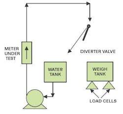
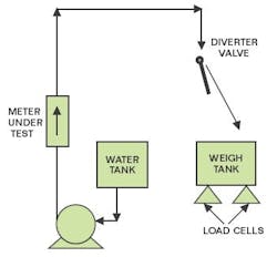
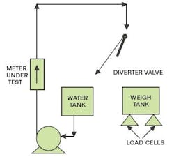
In a flow laboratory, flowmeters can be calibrated by flowing the same fluid through the flow laboratory calibration standard and the “meter under test” (MUT) that is comprised of a flowmeter primary and secondary. This can be done by circulating the liquid (Figure 1), diverting the liquid to a weigh tank (Figure 2), and then circulating again (Figure 3). By comparing measurements from the standard and the MUT (while diverting), the MUT can be adjusted (calibrated) to provide measurements that mimic the standard.
The flow measurement derived from a custody transfer flow measurement system is used to calculate the amount of money that changes hands between the past and present owner of the material. Residential water and natural gas meters that determine the homeowner’s consumption are a commonly encountered type of custody transfer flowmeters.In industry, custody transfer flowmeters are found in large numbers in the oil and gas industries. For example, flowmeters are used at the discharge of oil and gas wells to determine royalty payments and taxes thereon. Custody transfer flow measurement systems can also be used to determine the amount of petroleum products transferred between companies. Payments associated with some of these applications can involve the payment millions of dollars, so the ability to verify flowmeter performance is important. To put this in perspective, a calibration error of one percent of a $5,000,000 transfer is $50,000, so attention to detail and in-situ calibration can be important.According to Zaki Husain, Senior Engineering Specialist, Chevron-Texaco, Houston, Tex., “Many custody transfer installations in the oil and gas industry are calibrated in-situ using a flowmeter proving system.” A prover is a device that derives the flow rate by measuring the amount of time that an object, such as a ball or piston, travels through a known volume. Piping provisions are made to allow the prover to be installed in series with the flowmeter to measure the same flowing stream. Valves in the prover allow the flow to bypass the prover during the time that the prover is not measuring the flow rate. Due to the limited volume available in most in-situ provers, test times are relatively short and can be completed in just a few seconds. “In North America, the equipment and methodology used to determine payment is usually dependent upon the agreement between the parties,” Zaki adds. “Depending upon the agreement, the custody transfer measurement system could be implemented using such varied measurement systems as a 30-year old orifice plate with a circular chart recorder, or a precision positive displacement flowmeter with a microprocessor-based flow computer.”Depending on the agreement, these systems may or may not be calibrated using a prover.Paolo Fiorletta, General Manager, Metroval, Nova Odessa, Brazil, works for a company that makes flowmeters for custody transfer applications. Fiorletta says, “Governmental constraints have been placed on installations in Brazil, primarily to ensure that the proper amount of royalties and taxes are paid and to ensure proper development of the reservoir. Compliance with Brazilian regulations requires that the flow measurement system be designed to meet certain performance requirements and be calibrated on a periodic basis by qualified personnel.” As a result, in-situ calibration of the flowmeter system is virtually mandated in order to maintain performance during operation. Many other countries follow the same or similar regulations.Non-Custody Transfer ApplicationsMost flow measurement systems installed outside the oil and gas industry do not involve custody transfer, but rather monitoring and controlling flow. Therefore, the in-situ testing procedures described above are generally relaxed for the majority of these installations. The degree to which they are relaxed is dependent upon the nature of the application and the sophistication of the end user.In-situ flow calibrations of the entire flow measurement system (primary and secondary) are typically not performed for non-custody flowmeter applications. In many cases, only the secondary is calibrated because it is relatively expensive to perform an in-situ calibration of the primary. As a result, few flowmeter primaries are calibrated in-situ and it can be years until many of the primaries are even inspected.Matt Otto, Engineer, Bayer, New Martinsville, West Va., takes exception to this, stating that Bayer’s flowmeters are calibrated using a water source and a portable master flowmeter. “Piping connections to implement this type of calibration are routinely provided in new installations,” he says. For high viscosity applications, material is allowed to flow to a portable tote bin that is weighed. The weight of the tote bin is then compared to the flowmeter measurement. Environmental audits generally incorporate in-situ testing of applicable flowmeters that is performed by outside contractors.Roy Gregor, Component Engineer, Vermont Yankee Nuclear, Vernon, Vt., has mostly orifice plates and differential pressure flow transmitters to measure water flow rates. “The orifice plates are not routinely pulled for inspection because orifice damage would show up symptomatically as a low flow rate discrepancy when compared to other parameters monitored, such as differential pressure and temperature. The transmitters are calibrated using a ‘water pot’ onto which air pressure is applied.” This procedure is an in-situ calibration of the secondary. However, it does not constitute an in-situ flowmeter calibration because calibration of the primary is not performed. It tells you whether the pressure sensor and transmitter are working, but gives you no information about the state of the orifice plate or venturi.Juergen Amann, Instrument Supervisor, City of Tampa, Tampa, Fla., says, “Most of our magnetic flowmeters in sewage service are so large that wet testing them in-situ is impractical, so technicians can only calibrate the transmitters. In addition, the cost of returning primaries to the factory for calibration is excessive.” Juergen added that most flowmeters cannot be removed from service so it is difficult to gain access to even inspect the primaries. In some installations, material balances and historical information are used to verify the reasonableness of the flow measurements.Juergen and other flowmeter users in the water and wastewater industry have elected to purchase magnetic flowmeters with expanded diagnostic coverage. These flowmeters can monitor selected parameters in the secondary and primary, such as its associated electrical parameters. Variation from factory specifications would indicate a potential problem. The terminology vendors are using to describe these systems can be misleading. They provide in-situ verification of the parameters, the measurement of which may be traceable to a national laboratory such as NIST. However, these systems do not perform in-situ flowmeter calibration.An engineer in a northern USA cement plant says that his plant has “a few magnetic flowmeters that measure water flows, but there are no calibration procedures for them. Our stack gas flowmeters are calibrated by the manufacturer’s personnel, but I do not know if they are wet tested or not.”In-situ Calibration EquipmentWith the exception of flowmeter provers, most in-situ calibration equipment is designed to calibrate the flowmeter secondary, or transmitter. Some of these calibrators are designed to transfer calibration information to/from other systems such as maintenance management systems. Automating these information transfers can speed the availability of information, improve worker productivity, and reduce the number of errors that inherently occur in a manual system.John DuBay, Product Manager, Meriam Process Technologies, Cleveland, Oh., says, “Our calibrators address the calibration of the flowmeter secondary. The calibration procedures can be set up and scheduled using PC-based software and then downloaded to a handheld calibrator. The calibration can then be performed and automatically documented, yielding results which are then uploaded back into the PC-based software.” Other vendors produce similar systems. Documentation of the calibration can be paperless, and depending upon the system details, integration with computerized maintenance management systems and messaging systems may be possible.DuBay continues, “Electronic document control for the FDA can be implemented by associating a user with the handheld calibrator that performs the calibration.” This is accomplished by means of a pass code and user ID that must be entered to invoke the rights and allow validation of the handheld operator’s actions. This signing information, along with the calibration results, is stored in an audit trail that conforms to 21 CFR Part 11 requirements.Unfortunately, suppliers do not always offer a clear distinction between in-situ calibration and expanded diagnostic coverage. Expanded diagnostic coverage can improve flowmeter availability by continuously monitoring certain parameters and comparing them with historical values to detect and diagnose certain flowmeter problems in a timely manner. Implementing expanded diagnostics can be beneficial to help justify an increase in the time between calibrations. However, performing expanded diagnostic coverage does not provide an in-situ flowmeter calibration (as some suppliers might imply), so it is not a substitute for an in-situ flowmeter calibration and should not be represented as such.
Expanded Diagnostic Coverage
PERIODIC FLOWMETER verification and/or calibration are commonly used to maintain the availability of flowmeters installed in operating facilities. These approaches typically detect flowmeter problems after they occur, and often only after the flowmeter had a detrimental effect on the process.
To detect potential problems before they occur, the transmitter often contains self-diagnostics that verify its operation. While this approach may provide significant diagnostic coverage for the transmitter, it generally provides only rudimentary diagnostic coverage of the flowmeter primary.
However, some flowmeter suppliers are embedding diagnostics that verify the integrity of the flowmeter primary. In general, certain parameters associated with the flowmeter primary are measured in the field and compared with measurements made at the factory. As long as the difference between the factory values and field measurements remain within tolerance, the calibration of the flowmeter primary is presumed to have not shifted. Some expanded diagnostics are continuously monitored, whereas others are performed periodically.
Note that this approach is not a flowmeter calibration, but rather an in-situ flowmeter verification check that implies (but does not definitively determine) that the calibration of the flowmeter primary has not shifted. It can be likened to checking to verify that the condition and dimensions of an orifice plate have not changed, thereby implying that its calibration has not changed. However, this orifice plate check would not detect an out-of-round pipe, coating, plugging, or an obstruction that could change the calibration of the orifice plate flow measurement system. Even using physical inspection of the primary cannot detect out-of-round pipes, welding slag and burrs, a glove caught on the valve upstream, or other serious problems. Only an in-situ flowmeter calibration can do all that and make sure the flowmeter system is accurate and reliable.
Despite its limitations, expanded diagnostic coverage is an in-situ flowmeter verification tool that can improve flowmeter availability and extend intervals between routine calibrations/verifications. It cannot completely replace the actual calibration of a flowmeter system, either in-situ or at the lab.
For example, Micromotion (Emerson Process Management) recently announced the availability of expanded diagnostic coverage for its Coriolis mass flowmeters. They have found that verifying the density calibration by periodically filling the flowmeter with known fluids (typically water and air) implies that the flowmeter calibration has not changed due to product build-up or corrosion.
Some flowmeter suppliers such as ABB, Krohne, and Siemens can provide portable equipment to periodically check their magnetic flowmeter primaries for insulation resistance and other internal electrical parameters that are indicative of flowmeter primary problems. Krohne offers a transmitter with embedded expanded diagnostics that can perform these checks continuously.
| About the Author |
Latest from Home

Leaders relevant to this article:
