I'M A NOVEL instrument engineer, and I need some help: I’m trying to improve the level control of a 150,000 pounds/hr boiler, but I think the feed water valve is too far from the drum (100 feet away, there is a lot of dead time), Do you think the control will be better if the valve is relocated closer to the drum?
Alejandro Macías Hernández, Ingeniería de Mantenimiento
ANSWER:
WATER BEING incompressible, as soon as the valve opens to pass more water, more water will enter the drum. Because boiler feedwater and drum-level control are very important topics, I will discuss them in more detail below.
Feedwater control is the regulation of water to the boiler drum. This water is admitted to the steam drum and it generates the steam produced by the boiler. Proper boiler operation requires that the level of water in the steam drum be maintained within a certain band. A decrease in this level may uncover boiler tubes, allowing them to become overheated. An increase in this level may interfere with the operation of the internal devices in the drum that separate the moisture from the steam and may cause liquid carryover that can damage the steam turbine.
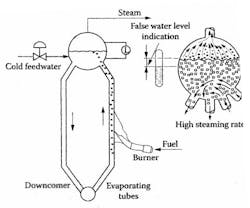
The water level in the steam drum is related to, but is not a direct indicator of, the quantity (mass) of water in the drum. At each boiler load there is a different amount of steam bubbles in the water. Thus, as load is increased there are more steam bubbles, and this causes the water to “swell,” or rise, rather than fall, because of the added water usage (See Figure 1 below). Therefore, if the drum volume is kept constant, the corresponding mass of water is minimum at high boiler loads and maximum at low boiler loads. The feedwater controls therefore need to respond to load changes and to maintain the mass of water, which requires to constantly adjust the water volume stored in the system.
FIGURE 1
Feedwater is always colder than the saturated water in the drum. Therefore, some steam is condensed when contacted by the feedwater. As a consequence, a sudden increase in feedwater flow tends to collapse some steam bubbles in the drum and temporarily reduce their formation in the evaporating tubes. Then, although the mass of liquid in the system has increased, the apparent liquid level in the drum falls. This is referred to as the “shrink” effect. Equilibrium is restored within seconds, and the level will begin to rise.
Nonetheless, the initial reaction to a change in feedwater flow tends to be in the wrong direction. This property, called “inverse response”, causes an effective delay in control action, making control more difficult. Liquid level in general can typically be controlled with a controller proportional band of 10 % or less. By contrast, the steam drum-level controller needs a controller gain closer to 1 (proportional band of 100 %) to maintain stability. Integral action is then necessary, which was not necessary, when narrow proportional band settings are used.
Control of feedwater on total drum level alone tends to be self-defeating, because during load changes, its action is the opposite of what is needed (a load increase causes it to decrease water feed when it should be increasing it). Boilers are designed for constant level operation, however.
For small boilers having relatively high storage volumes and slow-changing loads, a simple proportional control may suffice, imprecise as it is. Integral action should not be used, because of the instability that is a result of integration of the swell and shrink on load changes that must later be removed. Control of this type therefore involves the addition of feedwater on straight proportional level control.
For medium size boilers and particularly when there is a consistent relationship between valve position and flow, a two-element system can do an adequate job under most operating conditions. Two-element control involves adding the steam flow as a feedforward signal to the feedwater valve. Total level control is undesirable when it is detected by sensors that are insensitive to density variations, such as the conductivity type sensors. Displacement and d/p cell type sensors are preferred from this perspective because they respond to hydrostatic head. Smaller boilers, in which load changes may be rapid, frequent, or of large magnitude, will also require the two-element system.
In the two-element configuration, field testing, characterization, and adjustment of the control valve are required so that the relationship of control signal to feedwater valve flow matches that of the steam flow to the flow transmitter output. Any deviations in this matching will cause a permanent level offset at the particular capacity and less than optimal control.
Three Element Feedwater Systems
As boilers become greater in capacity, economic considerations make it highly desirable to reduce drum sizes and increase velocities in the water and steam systems. Under these conditions the boiler is less able to act as an integrator to absorb disturbances. A three-element system is used on such large boilers to arrest disturbances and react to load changes more rapidly.
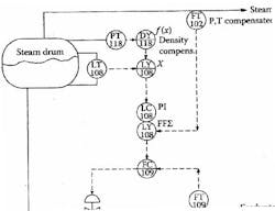
Three-element control is similar to the two-element system, except that the water flow loop is closed rather than being left open. In this way, pressure disturbances that would affect feedwater flow are handled immediately by the fast response of the feedwater flow loop. There are several ways of connecting a three-element feedwater system. Figure 2 below illustrates the most common way of connecting this system.
FIGURE 2Three-element feedwater system, plus density compensation with drum pressure.
In addition to the three primary control variables (three elements) -- drum level, steam flow, and feedwater flow -- drum vapor-space pressure can be utilized to compensate for density changes. The pressure is passed through a calculator, DY-118 in Figure 2 (above), that calculates a multplier to be applied to the raw level signal by LY-108. The value of the multiplier is obtained from the density change versus pressure for saturated steam, taken from the steam tables.
Gain adjustments of the three-element feedwater system are made by first determining the relative gains between level and flow loops. By observing a change in boiler load one can note the particular boiler “swell” characteristics. Maximum system stability results when the negative effect of swell equals the positive effect of flow. For example: If a 20 % of maximum flow change produces a 2.4 PSI (0.16 bar) change in a pneumatic flow transmitter output and this flow change also produces a 3 in. (75 mm) swell on a 30 in. (750 mm) range transmitter or a 1.2 PSI (0.08 bar) transmitter output change, then the gain of the level loop should be double the gain on the flow loop.
Feedforward Control
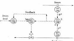
A feedforward variation is recommended by Shinskey to maintain a steam-water balance, reducing the influence of shrink-swell and inverse-response phenomena. The system shown in Figure 3 (below) causes feed-water flow to match steam flow in the absence of action by the level controller. The two flowmeters have identical ranges, and their signals are subtracted. If the two flow rates are identical, the subtractor sends a 50 % signal to the flow-difference controller. An increase in steam flow will call for an equal increase in feedwater flow to return the difference signal to 50 %.
Feedforward control of drum level.
Errors in the flowmeters and the withdrawal of perhaps 2.5 % water as “blowdown” (which is not converted to steam) will prevent the two flow signals from being identical. Any error in the steam-water balance will cause the level to fall or rise. Therefore, the level controller’s output readjusts the set point of the flow-difference controller to maintain the steady-state balance.
The system assumes the use of orifice-type flow sensors and does not use square-root extractors, because the period of oscillation and dynamic gain of a two-capacity level process varies directly with flow. This way the gain of the feedwater control loop is automatically compensate for the variations in process gain.
Figure 3 (above) also shows an external feedback from the flow-difference measurement, which is applied to the level controller. This preconditions the level controller during startup and when the feedwater controller (DFIC-109 ) is in manual it protects the level controller from reset windup. Otherwise, an increase in steam or blowdown flow will immediately increase the feedwater flow, without depending on the level controller. This means that the feedback portion of the loop (LIC-108) will need only to trim the DFIC-109 set point to correct for flow metering errors.
In this configuration, the level upsets are minimized, because the role of the feedback portion of the loop is reduced from manipulating feedwater flow across its entire range to adjusting it for flow meter errors only. In this configuration, controller mode settings are not critical and inverse response caused by shrink, swell are also reduced.
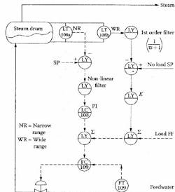
FIGURE 4Wide ranging proportional feedback drum level control, to help reduce performance degradation due to shrink-swell effect.
Shrink-Swell Compensation
Another variation of steam drum level control proposed by Shinskey to overcome shrink-swell effects involves the use of proportional feedback from a level measurement that detects a wide range (LT-108b). On large boilers, primary drum level control is often accomplished with a narrow-range transmitter (LT-108a) for more accurate control, with a wide-range transmitter present to respond to large excursions and handle alarm trips outside the narrow control range.
The wide-range transmitter can be utilized to provide proportional feedback to sum with the output of the narrow-range level control (LC-108). When an increase in load, causes the water to swell, the wide-range measurement, which is sensing much more of the total water inventory, will tend to give a lower measurement, while the narrow-range instrument may indicate a rising level. Used with the proper filtering and tuning, the wide range signal can be used to offset the narrow-range control loop's inverse response.
Bela Liptak, CONTROL Columnist

Leaders relevant to this article:


