By Richard A. Furness and David W. Spitzer
Sometimes data flies in the face of what we’ve been taught for generations. People thought the earth was “flat” for most of recorded history. Its flatness was accepted as fact (at least by all but a few of the most forward-thinking people) until it was mathematically proven otherwise. Only in 1492, did Columbus sail the “ocean blue” in a westerly direction to find a path to India, and even then he didn’t succeed. Pictures of the round Earth became available only 40 years ago as a byproduct of space exploration and courtesy of NASA’s Apollo missions.
Now we’re confronted with the another “flat Earth” meme, this time in the case of flow measurement. What we “know” regarding upstream straight run distances and what we’ve recently found appear to be in conflict.
What We “Know”
Flowmeter operation is based on geometry in conjunction with a measuring principal. For example, differential pressure flowmeters present a restriction to the flow across which a differential pressure related to the flow rate is produced. Generating the proper differential pressure depends on the presence of a fully developed, uniform, symmetrical and non-swirling velocity profile upstream of the flowmeter.
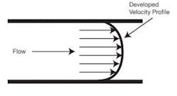
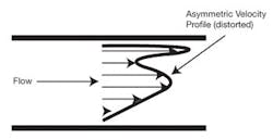
Distorted velocity profiles, such as those occurring downstream of a pipe fitting or throttling valve, can change the relationship between the flow rate and the differential pressure produced, because the swirl causes unpredictable and unstable velocities at the pipe wall that manifest as pressure changes that affect flow measurement. Similarly, multiphase flow conditions can alter this relationship, but in a different way (Figures 1 and 2).
Figure 1. Developed velocity profile free of distortion. This is an ideal difficult to reproduce outside of textbooks.
Figure 2. Distorted velocity profile caused by unstable and unpredictable velocities at the pipe wall.
One method of generating a fully developed, uniform, symmetrical and non-swirling velocity profile is to allow the fluid to flow in an infinitely long straight pipe. This geometry allows distortion produced after fittings, valves and pumps to attenuate and produce a velocity profile similar to that presented in textbooks, standards and installation guides. However, this installation is impractical due to its excessive length.
From a practical standpoint, flow profile effects can be reduced if sufficient pipe diameters of straight run are installed upstream of the flowmeter so any remaining distortion present doesn’t affect the flowmeter significantly. The upstream straight run required varies with flowmeter technology and the complexity of the upstream piping configuration—and more than the nearest fitting to the flowmeter needs be considered. The minimum upstream straight run requirement for a given flowmeter, piping configuration and size can be determined by testing the flowmeter with different lengths of upstream straight run. Testing generally shows that the upstream straight run (expressed in pipe diameters) required is essentially independent of pipe size. Therefore, the minimum number of straight runs required to achieve accurate flow measurement typically is expressed in pipe diameters and published in tables or graphs. As such, standards do not give adequate guidance on the effect of pipe diameter on flow measurement—especially in sizes above 24 in.
In the previous century, the rule of thumb was to install flowmeters with 10 diameters of upstream straight run and five diameters of downstream straight run. A more detailed investigation of the requirements for different flowmeter technologies reveals that some flowmeters require longer straight runs, while others operate properly with less. Excessive straight runs can have economic penalties in installations where acceptable flowmeter accuracy can be achieved using a shorter upstream straight run. However, insufficient straight run can adversely affect the performance of a flowmeter installed with only 10 diameters of upstream straight run This is especially true where 40 diameters (or more) are required for accurate flowmeter operation, such as when a large-diameter orifice plate is downstream of multiple bends.
Though it’s incomplete because initial testing was only done on small pipes, this body of knowledge was developed over decades, and it’s presented in textbooks, standards and installation guides. It shows that a flowmeter installed in a piping configuration requires a minimum number of diameters of upstream straight run to ensure accurate flow measurement. This distance was shown to be adequate for the decay of disturbances in pipes smaller than approximately 12 in. Further, it’s generally accepted (but not stated) that the straight run requirement (expressed in pipe diameters) is independent of pipe size. Stated differently, the number of upstream pipe diameters required for accurate measurement is independent of pipe size.
What We Found
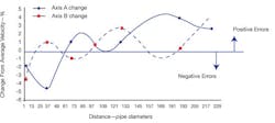
Recently, experimental work in several parts of the world has yielded a different picture. Flow velocities at right angles to each other were measured along a 200-diameter section of straight 48-in. pipe in South America. Given what we “know,” we’d expect to measure indications of velocity profile distortion (velocity error) within the first few diameters of pipe (say 5Ds to 15Ds), and a uniform velocity profile downstream of this section after the distortion attenuates.
The results of velocity testing (Figure 3) show that indications of velocity profile distortion extend throughout the entire 200-diameter section without any reduction. The magnitude of the velocity errors was between -4% and +4%, depending on position along the pipe section. Also, the velocity error actually increased beyond 100 diameters!
Figure 3. Flow velocity errors in a 48-in. straight pipe.
These results are explained by the presence of rotational distortion (swirl) that doesn’t readily attenuate in large pipes. Flow testing indicates that swirl is attenuated in relatively small pipes because that swirl is in relatively close contact with the pipe wall, so the effect of wall friction influences all parts of the flow area. However, in large pipes, the swirl has far less contact with the pipe wall. In one of our studies of a large pipe (over 4 meters in diameter), the pipe wall had a negligible influence in the main body of the flow. By way of explanation, the momentum inherent in the swirl increases with the mass flow (in three dimensions), whereas the pipe wall surface increases with its area (in two dimensions). Therefore, the ability of the pipe wall to attenuate swirl should decrease as pipe diameter increases.
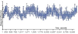
A large differential pressure flowmeter in North America was installed with its recommended 5 diameters of upstream straight run. Operators reported differences between flow measurements made on opposite sides of the flowmeter, which we subsequently confirmed by more detailed experimentation. One would expect that pressures on both sides of the flowmeter to be identical. However, the pressure difference between taps on opposite sides of the pipe were quite different and oscillated (Figure 4). The operators also found that introducing a flow upstream of the bends affected the flow measurement by as much as 10%. Please note that this observation is anecdotal and hasn’t been tested rigorously.
Figure 4. Measured pressure difference between opposite sides of pipe.
In this installation, the flowmeter was installed downstream of two large bends located within 2 diameters of one other. A general rule of thumb is that fittings within 5 diameters of one other generally create swirl. Bends in different planes, complex valves and pumps are similarly troublesome, and generate different profiles in different planes at the same position along a pipe. The differences in the static wall pressure at the flowmeter inlet, plus the oscillating pressure difference between upstream and throat taps on opposite sides of the pipe, is an indication of the presence of bulk swirl in the line.
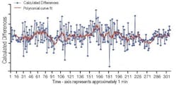
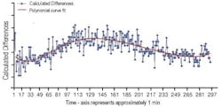
The differences between flow measurements taken on opposite sides of the flowmeter also oscillated with different periods under high and low flow conditions (Figures 5 and 6). In particular, doubling the flow reduced the period of oscillation by about half, while the flow measurement bias errors varied from –1.5% to +1%. This shows that swirl depends on flow rate.
Figure 5. Calculated flow differences – high flow.
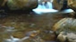
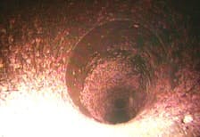
Furthermore, physical data also is available to support the premise that swirl propagates down large pipes more than just a few pipe diameters. Consider the photo of the interior of a 100-year-old water pipe installed as part of a water supply system in North America (Figure 7).
Figure 6. Calculated flow differences – low flow.
The pattern of encrustation on the pipe wall follows the average motion of the fluid over the century and reflects the presence of swirl in the flowing stream. The flowmeter in this particular installation exhibited flow measurement errors that equate to millions of dollars of revenue. Theory developed in the 1950s in the U.K. hinted this may be the case, and now we’ve observed it.
Figure 7. Swirl encrustation “fossilized” onto straight pipe wall.
What Next?
The extent to which swirl can be present in large pipes calls into question what we “know” about the upstream requirements for flowmeters in large pipes. The magnitude of the potential flow measurement errors caused by these results can be significant—regardless of flowmeter technology. Further, the upstream straight run requirements in flowmeter standards and manufacturers’ recommendations may be woefully inadequate to reduce the influence of swirl in large pipes effectively. Further investigation is necessary (and is on-going) to quantify these effects and/or develop standardized techniques to detect and mitigate the effects of swirl in large pipes. We plan to report the findings as the data is gathered and analyzed.
David W. Spitzer, Spitzer and Boyes, LLC
845-623-1830 or www.spitzerandboyes.com
Richard A. Furness, PhD, CEng, JDF & Associates Ltd
44-145-278-0893 or www.jdfandassociates.com
Latest from Flow

Leaders relevant to this article:
