In other words, our collective memories are short. Our hunger for profits has erased the memory of not only the BP accident, but also of Exxon Valdez, and we do not care about the future, when the sun will keep coming up, while gas and oil will not.
Since it seems that the drilling for oil and gas will be with us for some time, the only contribution our profession can make is to improve the safety of these processes. We can't change such facts as, for example, that in areas where fracking is taking place, the number of allergy patients tripled, or that an area of ice equal to Europe has already melted in the North Sea, but we can make the drilling process safer.
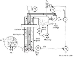
Here I will describe how the conversion from the present, largely manual operation of well drilling, can benefit from automation. The key to the safe operation of the drilling process is a good understanding of a simple process, the operation of a flow loop in a pressurized "U-tube." The drilling fluid that is circulated in this loop (also called formation fluid or drilling fluid) consists of water and additives. It is first pumped down into the well through the inside of a drill pipe, and is directed to return back up on the outside of the drill pipe in an annulus (the space between the drill pipe and the well bore). As the drilling fluid rises back up and enters the mud tank (Figure 1), it is also bringing up the rock fragments (cuttings) that the drilling into the rock layers produces. This circulation continues until the desired depth is reached.
Figure 1: The key to the safe well drilling operation is to keep the drilling fluid pressure (Pdf) above the bottom pressure (Pb), but below the fracking pressure of the drilled formation (Pfr).
The rock fragments brought up from the well are removed by shakers, while the drilling fluid is returned from the mud tank to the suction of the mud pump, which pumps it down again into the well through the drill pipe. The circulating drilling fluid is under high pressure (up to a maximum of about 15,000 psig). The drilling fluid pressure (Pdf) is generated as the sum of the elevated suction pressure of the mud pump (because the mud tank is pressurized by high- pressure nitrogen) and the pressure added by the variable-speed pump. In an automated system (most wells now are drilled under manual control), the pressure of the drilling fluid (symbolically controlled by PC in Figure 1) can be kept on setpoint by modulating the pressure of the nitrogen blanket on the mud tank.
In operating the drilling process, the critical control loop is this pressure control (PC) loop because on the one hand the pressure of the drilling fluid (Pdf) has to be below the fracking pressure (Pfr) so that the drilling fluid does not escape, and on the other hand, it has to be above the bottom hole pressure (Pb), so that a kick in hydrocarbon pressure at the bottom of the well does not result in oil or gas entering the annulus and possibly even blowing out the drilling fluid. Because both of these limit pressures (Pfr and Pb) can change as the drilling advances through different rock formations that might contain oil or gas at different pressures, the fluid pressure must be kept within Pfr and Pb and must respond to these variations quickly and accurately. Whether the pressure of the drilling fluid (Pdf) (the measurement of PC in Figure 1) is within Pfr and Pb can be determined automatically on the basis of the in-and-out flows from the well. Doing this automatically (which generally is not done), would make well drilling much safer.
A need for increasing the drilling fluid pressure (Pdf) is indicated if more fluid returns from the well (FR) than the amount pumped into it (FR > FC in Figure 1), or if the level in the mud tank (LC) is rising. These conditions indicate that the Pdf is lower than the hydrocarbon pressure at the bottom of the well (Pb) and, therefore, the drilling fluid pressure (Pdf) must be increased to stop the hydrocarbons from entering the well.
Inversely, Pdf must be reduced if the flow of the returning drilling fluid is dropping substantially (FR < FC), or if the level in the mud tank is dropping quickly. Small losses of drilling fluid are normal, as liquid is lost with the removed rock fragments and due to normal leaks into the rock formation. But, when the required injection of make-up fluid (containing the required chemical additives) rises in order to keep the level constant (LC in Figure 1), the pressure Pdf is too high. Therefore, if the loss is large, that indicates that Pdf is too high (higher than the fracking pressure of the formation, Pfr), and must be reduced. Otherwise this can cause the complete loss of circulation.
My recommendation for measuring the drilling fluid flows (FC and FR in Figure 1) is to use Coriolis flowmeters, because they are accurate, have high rangeability, and can also detect density, so that one can also measure (and control) the rock loading of the returning drilling fluid. Without control, this loading can vary too much, even if flow and pressure are kept constant, because of the changing nature of the rock formation being drilled.
The velocity of the drilling fluid at the drill bit has to be high enough to carry up the rock fragments through the annulus. This velocity can be automatically changed by adjusting the flowing volume (controlled by FC in Figure 1, which throttles the pump speed). The two control loops (PC and FC) interact because a change in pump speed changes both the flow rate and the discharge pressure of the pump. Therefore, decoupling of these loops is needed. The algorithm for decoupling the fast FC and the slow PC control loops is not shown in detail in Figure 1, only implied by block D.
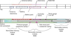
Figure 2: Battery-operated drilling sensor sub (DSS) sensors measure and memorize the weight on bit, torque on the bit, pressures and temperatures in both the drill pipe and the annulus for the period of a drill run (about 100 hours).
Courtesy of the Oild Drilling Program, Texas A&M University.
In addition to safely controlling the drilling fluid flows, pressures, rock loading and mud tank level, it is also important to accurately measure the drilling and coring parameters near the bit during the drilling operation (Figure 2). These parameters can be measured by the drilling sensor sub (DSS), which than helps to improve down-hole tool performance.
The DSS sensors measure weight on bit, torque on bit, annulus and internal pressures and temperatures. The data is collected as a function of time by the down-hole electronics, and is stored in its memory until the bottom-hole assembly (BHA) is retrieved. The DSS has an 8.25-in. outer diameter, while its inner diameter is 4.125-in., accommodating the drill string used in the retrieval of the core.
The sensors, data acquisition electronics and lithium batteries needed for about 100 hours of operation are packaged in the DSS sub wall. The sensor data is collected by the down-hole electronics, and stored in memory until the bit and BHA are retrieved at the end of the coring run. At that point, the data is downloaded, evaluated and used to improve the operation of the next run.
