This column is moderated by Béla Lipták (http://belaliptakpe.com/), automation and safety consultant, former chief instrument engineer at C&R and former Yale professor of process control and editor of the Instrument Engineer's Handbook. If you have automation related questions for this column, write to [email protected]
Q: My question is this: Can we replace a P controller with a linear function generator in controlling the level on a deaerator?
General information about the control loop(s):
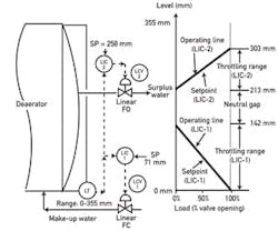
- The issue is related to a deaerator (DA) level control. There are currently two loops controlling the DA level, i.e. the make-up control loop and valve and the surplus control loop and valve. The setpoints of the loops are set at 142 mm and 213 mm, respectively. The total DA level range is 0 mm to 355 mm. Make-up water is supplied indirectly to the DA, i.e. it will go first through the condenser and condenser level loop. The surplus goes back to the condenser.
- The loop design specification states that there should be a linear relation between the level control error and the corresponding valve's position. The position of the make- up valve should be between 0% to 100% for a corresponding level error range of 0 mm to 142 mm; it should start controlling when level falls below 142 mm; and fully open when level reaches 0 mm. The position of the surplus valve should be 0% to 100% for a corresponding level range of 213 mm to 302 mm; that is, it should start controlling when level increases above 213mm, and fully open when level reaches 302 mm.
- Between 142 mm and 213 mm both valves should be closed.
- Due to above requirements, P controllers have been used for both make-up and surplus loops, with gains of 2.5 for the make-up and 4.0 for the surplus. Both loops are implemented in digital control system (DCS) controllers.
The operational issues:
Do you agree with the proposed change? What control issues could that change generate? Any suggestions for any changes in the loop would be very welcome.
Guido Villacis
[email protected]
A: Gap level control can be provided by using two controllers or by splitting the output of a single controller among two valves with a gap in the center of the control signal where both valves are closed.
Therefore, whenever the required valve opening (the load) changes, an error must develop, and this error is called the "offset." For example, if the load "m" has changed to 60%, while the normal load (b) was 50%, the offset error is Offset Error = (60% - 50%)/(controller gain). Consequently, if the controller gain is high, (the slope of the operating curve in Figure 1 is steep), and proportional control is acceptable because the level will not change much while the valve is throttled (the offset is small).
Therefore, as shown in Figure 1, the two-controller system will "bump" the valve by the amount of the offset when the loop is switched between manual and automatic, but this does no harm to the level control, and the operator should simply be educated to accept it.
Another option is to provide logic that guarantees bumpless transfer, but it will not improve the quality of level control, only eliminate the "offset bump."
The correct system parameters are listed in Table 1.
Béla Lipták
[email protected]
A: I'm guessing that the current implementation does not use true P controllers. Digital systems based on incremental (velocity) algorithms have a floating output bias that changes whenever the controller is placed in manual or hits a limit. True proportional control is what you need, and you can get it with simple linear functions. The only caveat is that you can't transfer bumplessly from manual to auto. But it will control level. Teach the operators to accept the variable offset.
Greg Shinskey
[email protected]
A: It sounds to me like the P controllers rebalance their bias term when the controller is in manual mode. Some control systems allow the option of disabling the bumpless rebalance. (I do not know what is meant by "tripping" to manual, or what would cause that. A boiler trip to no fire? The deaerator level must always be controlled, no? A leaking valve could fill or drain it.)
If the disable option does not exist, by all means use linear function generators (characterizers) to provide the required control action.
I'd build in some dead band, so that the valve does not creep off its seat near zero. Let it get a few percent away from zero output, and then pop it open to the required percent. Do this by putting a kink in the function. This is not usually possible in a P controller.
The function generator will not provide any way to rebalance during manual mode. Even if it did, the rebalance is not desired because it would bias the function, as it does now with the P controllers. That is, you do not want bumpless transfer to a calculated value. The operator should adjust the valve to the calculated value before resuming automatic operation. Actually, this will work with the P controllers, if the bias value is displayed, so that the operator can manually adjust the output to make the bias value go to zero.
Foundation fieldbus control blocks use a timed ramp to bring the manually set output back to the calculated value on transition to auto. This provides a bumpless transfer that uses the ramp to bring the valve to the calculated value without adding a permanent (until the next transition to manual) bias. Perhaps blocks are available to do this in the control system that is being used.
If the number of function blocks is not constrained, another way to solve this is to build two function generators, and connect a PI valve position controller between the function output and the valve. If the operator needs manual control of the valve, the PI will rebalance to zero error at the integral rate when automatic control is restored.
Bill Hawkins
[email protected]
A: I believe the problem is related to bumpless transfer.
Some controllers have a feature called "setpoint tracking" (some manufacturers call this "PV tracking"). This means that the setpoint does not remain constant always, but when the controller is in manual, the SP is forced to whatever the current PV is. So when the operator changes back to auto, the SP and PV are already equal, hence there is no "error," therefore, no change in valve position. This is one way of achieving bumpless transfer, but it is not the only way.
I assume—and hope—that you do not have setpoint tracking on your system. If the operator sets a setpoint of 40% (displayed as 142 mm), then that setpoint stays there. If this is the case, bumpless transfer must be achieved in some other way.
A proportional control algorithm first determines the error (SP - PV, for a reverse acting controller-makeup valve) or (PV - SP, for a direct-acting valve-surplus loop), where both PV and SP are in % of measurement value. (That is, 142 mm = 40% of 355 mm, 213 mm = 60% of 355 mm. Then the controller output is computed as (controller gain x error + an added value which I will call "bias"). This "bias" is an operator-adjustable setting on some controllers; on others it is not. In essence, the bias value is the signal sent to the valve when the controller is in auto and the SP and PV are equal.
The manual-auto switch comes after the normal control algorithm, so in what follows, I will talk about two different outputs:
- The controller output, which is the signal sent to the valve, whether the controller is in Auto or Manual
- The control algorithm output, which is the computed output that is used if the controller is in Auto.
Consider the make-up controller. You want the controller output to be 0% (valve closed) when the PV is at 40% (142 mm). At that point, there is 0% error, so the bias value should be 0%, and it should never be changed; that is, you do not want bumpless transfer.
Consider this. Suppose the level is at 71 mm (20%). The error is 20%. (SP is at 142 mm, or 40%. SP - PV = 40% - 20% = 20%.) If the controller is in Auto, the controller output would be Error x Gain + Bias = 20% x 2.5 + 0% = 50%. But suppose the controller is in manual and the operator has set some other value for valve position, say 55%. In order to have bumpless transfer, the controller has to change the bias to 5%, so that the control algorithm output matches his manual setting. (Error x Gain + Bias = 20% x 2.5 + 5% = 55%). Now, when PV = 40% (the SP) the valve will be 5% open, not 0 % open, as you desire.
If you did not have bumpless transfer, in the situation above (the PV is at 71 mm, the controller is in manual, and the operator-set valve position is 55%), when the operator goes to auto, the valve position will go to 50%. There will be a bump, but the operator will know what the controller is doing at all times.
Going to a linear function generator will not help. A proportional controller without bumpless transfer is already a linear function generator. Going to a linear function generator, then implementing the logic for bumpless transfer will get you right back to the place you are now.
I would seriously consider why the system ever trips to manual. What has gone wrong to cause that. Could there be additional controls that would mitigate these circumstances? I'm thinking of something like a feed-forward action here. I think there should be an in-depth analysis of the entire system, plus some operator training. I have seen cases where operator understanding of the system went a long ways toward solving problems.
Harold Wade
[email protected]
A: The control scheme that you describe is a bit different than what we would typically implement for deaerator level control. In our implementation we would use a single level controller whose output would drive the two valves in a split-range fashion. In some applications, we would also add a feed-forward to the controller based on deaerator outlet flow. If the specification for your control scheme is as you describe, however, there is no reason why you could not use linear function generators in place of the proportional-only controller if you provide the manual-auto transfer related functions with additional logic.
Dale Evely
[email protected]
Southern Company

Leaders relevant to this article:


