In the next articles, I will continue this series by showing what automation can do for oil sand processing/pipelining.
Here I will not discuss the environmental damage drilling in the Arctic can cause nor the risks to the crew due to ice and insufficient winterizing. I will only focus on what optimized process control could do to protect the ships from storms and hurricanes by automatically stabilizing them while drilling.
Drilling ships have to pass through the Bering strait, which is open only during the summer. The storms in the Arctic Ocean are powerful. In the past, waves up to 40 feet high and wind gusts of 89 mph have been reported, and these storms are becoming more powerful as the planet is warming. Just last December, a Russian drilling ship working near the island of Sakhalin capsized, and 49 of the crew of 67 were lost.
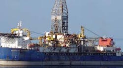
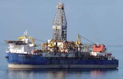
Figure 1: The drillships are working in open water, held in place by winch-operated chain-rodes that act as the "control valves" of this position-control loop.
Therefore, to keep the ship in place is critical. As can be seen in Figure 1, movement would break the vertical pipes that connect it to the well if the dozen or so anchor rodes (shown in Figure 4) were not automatically and correctly controlled. I will explain why the present semi-manual methods of stabilizing are inadequate, and will describe the automatic optimization strategies that should replace them.The Stabilization Control Envelope
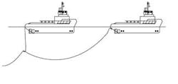
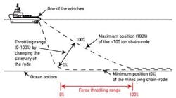
The ship is stabilized by a dozen or more anchor rodes made from chains which are several miles long (Figure 2) and weigh over 100 tons. This dynamic stabilization allows the ship to move in three dimensions—to yaw, pitch, roll and drift—without breaking the flexible pipes that connect it to the well. This is because its position is held inside a three-dimensional "safe envelope" that never moves further away from the well than a safe distance.
Figure 2: The installation of the "control valves," the several miles long chains weighing over 100 tons (called rodes) require several ships.
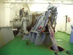
The present method of semi-automatic stabilization is to pull in the rode chains that are facing the direction of the wind to increase their "pull," while "paying out" the rodes on the opposite side of the ship.The relationship between the force generated by this pulling that changes the "rode catenary" and the push of the storm is well understood. While the wind force is not constant, its strength and direction constantly changes, theoretically it can be perfectly balanced if the rodes are heavy enough and if the manipulated winches (Figure 3) are strong and fast enough. In other words, what we need to apply is classic multivariable envelope control (Chapter 8.6 in Volume 2 of the 4th edition of The Instrument Engineer's Handbook).
The limits of this envelope are the allowable distances from the well. One method to implement that control is to use my "Hungarian Puli" algorithm. The puli is a livestock herding dog that keeps the herd together and moving in the right direction by going after only one sheep at a time. This is always the one that is moving in the least desirable direction (closest to the limit of the control envelope). So in this application, we "go after" the rode that is able to pull the ship away from the closest limit of the envelope.
Figure 3: The "control valve actuators and positioners" are the winches which can lift over 100 tons and serve to "throttle" the tension in and catenary of the dozen or so individual chain-rodes.
The setpoints of this multivariable control loop are the distances from the borders of the envelope, and the manipulated variables (the control valves) are the winches. It is desirable to put positioners on these "valves," which will compare the actual pay-out lengths and tensions in the rodes with the required lengths, and will reposition them if necessary.The controlled process is the ship, and the load is the wind force. The dynamics of the process are a function of the ship's inertia, response time and speed of response (process gain = GP). The rode tension sensor has its own gain (GTS), and so does the manipulated variable, the winch (GW). Therefore, in order to properly control this loop, we must correctly "size the valve" (make the winch powerful enough). We also have to select the right winch gain (GW). It has to provide a fast enough response, and has to have a variable speed to compensate for the variable gain (GP) due to the changing load (the changing force and direction of the wind). Knowing these gains, we can "tune the loop" by adjusting the gain of the rode position controller (GPC), so that the loop gain (GL) will be about 0.5. {GL = (GP)(GTS)(GW)(GPC)}.
Adding Feedforward to the Control Envelope
CLICK ON IMAGE TO ENLARGE
Stable operations
Figure 4: The control algorithm that sends the individual
setpoints to the winches keeps the ship inside a
3-dimensional safe operating envelope which is
"feedforward adjusted" as a function of wind strength
and direction.
Courtesy of Roy E. Floysvik/Norwegian Petroleum Museum
The strength and the direction of the force generated by the wind is constantly changing. Therefore, to stabilize the ship, the previously described PID tuning by itself is insufficient. "Anticipation" (feedforward) must be added to it. This means that we must continuously measure the dynamics of the wind (the load) and as soon as it changes, we must start responding to it (Figure 4).
Naturally, this requires a sophisticated computer model, which could theoretically be prepared by scientists (weather scientists, naval architects, etc.), but I would not do that. I trust Murphy's Law more than science. I would simply install a self-teaching artificial neural network (ANN) algorithm model (Chapter 2.16 in Volume 2 of The Instrument Engineeer's Handbook) and let it develop the process model automatically just by watching what is happening in the real world.
Just as in case of all other new industries, here too we have to overcome the hurdles of secrecy and ego. In some corporations there is a policy of not letting outsiders "stick their nose" into what they are doing, and there is also a sense of pride that they "know better." These emotional and public relations hurdles can only be overcome if our profession proves that it can offer real benefit to the off-shore drilling industry. If we could show them that applying the know-how, we have accumulated by automating the traditional industrial processes for a century is practical, we could prevent accidents such as Deepwater Horizon or Sakhalin.
