Understanding how ultrasonic continuous level measurement works

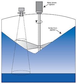
Figure 2. Sometimes the measured value is "what the level would be if the agitator were turned off."
The five non-contacting level measurement technologies are radar, nuclear, laser, weight and ultrasonic. Each of them has both good points and bad. Radar, for example, is relatively expensive in the more accurate versions (frequency-modulated, continuous-wave, FMCW), while nuclear level is limited to relatively small vessels, and there are licensing and safety considerations. Lasers appear to have developed an application niche, especially in the measurement of bulk solids and powders. Weighing systems can be used in some vessels, but it is, again, a relatively niched application solution. Of all of these, ultrasonic level measurement is the most widely used non-contact technology. Ultrasonic level transmitters are used in most industries and are very widely used in open-channel flow measurement systems, sited atop a flume or weir.
How Does It Work?
Ultrasonic level sensors work by the "time of flight" principle using the speed of sound. The sensor emits a high-frequency pulse, generally in the 20 kHz to 200 kHz range, and then listens for the echo. The pulse is transmitted in a cone, usually about 6° at the apex. The pulse impacts the level surface and is reflected back to the sensor, now acting as a receiver (Figure 1), and then to the transmitter for signal processing.
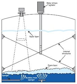
Figure 3. Bubbles, foam, vapor and internal structures make ultrasonic measurement very difficult.
Basically, the transmitter divides the time between the pulse and its echo by two, and that is the distance to the surface of the material. The transmitter is designed to listen to the highest amplitude return pulse (the echo) and mask out all the other ultrasonic signals in the vessel.
Because of the high amplitude of the pulse, the sensor physically vibrates or "rings." Visualize a motionless bell struck by a hammer. A distance of roughly 12 in. to 18 in. (300 mm to 450 mm), called the "blanking distance" is designed to prevent spurious readings from sensor ringing. This is important for installation in areas where the distance above the level surface is minimal.
Physical Installation Issues
There are some important physical installation considerations with ultrasonic level sensors.
- Make sure the materials of construction of the sensor housing and the face of the sensor are compatible with the material inside the vessel. Most ultrasonic sensor vendors provide a wide selection of sensor materials of construction in case the standard sensor housing isn't compatible. Most sensors come with a PVC or CPVC housing. PVDF, PTFE (Teflon) and PFA (Tefzel) are usually available. In some cases, a housing of aluminum or stainless steel with a polymer face can be provided.
- Make sure that the operating temperature range of the sensor is not exceeded on either the high or low temperature end. The materials of construction may deform or the piezoelectric crystal may change its frequency if the temperature range is exceeded. The change in ambient temperature is usually compensated, either by an embedded temperature sensor, a remotely mounted temperature sensor or a target of known distance that can be used to measure the ambient temperature.
- Locate the sensor so that the face of the sensor is exactly 90° to the surface of the material. This is especially important in liquid and slurry level measurement. In some bulk solids measurements, this can be modified (and this will be discussed in a later section of this article). If you do not do this, your echo will either be missed entirely by the sensor, or it will use an echo that is bouncing off the vessel wall or a vessel internal structure instead of the real level.
- Make sure that the vessel internals do not impinge on the pulse signal cone from the sensor. If they do, you may get a spurious high amplitude echo that will swamp the real return echo from the surface of the material.
- Make sure you avoid agitators and other rotating devices in the vessel. Sometimes you can do this with an additional waveguide. If you can't, make sure you purchase a transmitter that can compensate for the effects on the echo of the agitator blade moving in and out of the signal cone.
- Mount your sensor where it can't be coated by material or condensation inside the vessel. Coatings attenuate the signal, sometimes so much that there is no longer enough power to get through the coating to the surface and back. If it isn't possible to avoid coatings, try to provide some means of cleaning the sensor face. Some transmitters provide a signal "figure of merit" that can be used to detect coatings or other signal failures and activate an alarm function.
- Always use the vendor-supplied mounting hardware for the sensor. Hard-conduit-wiring an ultrasonic sensor can increase the acoustic ringing and make the signal unusable.
Application Considerations
Because ultrasonic level sensors and transmitters are inexpensive and usually easy to install, they're often used at the outer edge of the application envelope, and erratic or erroneous signal and signal failure often result.

Ultrasonic Open-Channel Flowmeters
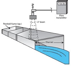
One of the most important applications for ultrasonic level sensors and transmitters is measuring open-channel flow (figure 4).

Most of the same caveats apply to ultrasonic level sensors used as flowmeters as apply to ultrasonic level sensors used as tank level measurement devices. There are a few more:
- Avoid wind and sun. Wind can blow through the vapor space and attenuate the signal or blow it off course. Sun can raise the temperature of the sensor housing itself beyond the operating temperature range of the device-and higher than the ambient temperature.
- Make sure that there isn't foam on the surface. This can happen often in nitrifying wastewater discharges.
- Make sure that there is not too much turbulence or ripples (or if the flume or weir is large enough, wave action) on the surface.
- Above all, make sure that the flume or weir is installed correctly. Many problems blamed on the ultrasonic transmitter are actually problems that are caused by the flume not being installed level both horizontally and vertically, as well as front to back through the measurement zone.
- Make provisions to keep ice from forming on the sensor in the winter or dripping condensation in the summer.
The One-Trick Pony--Not!
Ultrasonic sensors are simple to understand, easy to install and inexpensive. It's easy to go to them as the unthinking sensor of choice for level applications, just as many people go to differential pressure level sensors. Yet, as many users have found, ultrasonic sensors and transmitters are tricky beasts. As with any other field instrument, applying an ultrasonic level sensor too far outside the manufacturer's recommended application envelope is destined to fail, and sometimes fail spectacularly. But, if you follow these basic guidelines, you will have successful ultrasonic level installations.
