Proof test coverage (PTC) of safety instrumented systems (SIS), also known as CPT, has recently become an important topic of discussion. PTC can be defined as the fraction of dangerous, undetected failures that can be detected by a user proof test and is normally expressed as a percentage (%). In the past, it was commonly assumed in calculation and in practice that proof test coverage was 100%. However, not all proof tests are comprehensive, and the approval agencies often indicate that the recommended proof test does not have a 100% PTC, new out of the box.
The PTC concept applies to both partial and complete proof tests, and PTC is calculated as shown in Equation 1:
PTC% = (dangerous undetected failures detected by the user proof test / total dangerous undetected failures) x 100 (1)
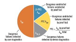
The device dangerous failure regime (Figure 1) shows the different failure modes when proof test coverage is included. By default, (1-PTC)% is the estimated fraction of dangerous, undetected failures that are not detected by a user proof test. We're primarily interested in (1-PTC)% because that's what we'll have to address because the PTC of our devices affects the reliability of the SIS.
Figure 1: The device dangerous failure regime shows the different failure modes when proof test coverage is included. By default, (1-PTC)% is the estimated fraction of dangerous, undetected failures that are not detected by a user proof test. We are primarily interested in (1-PTC)% because that is what we will have to address.
Effect of PTC on PFDavg calculation
Simplified equations can show the effect of PTC on calculations of the average probability of failure on demand (PFDavg) for a single device. Without PTC, the PFDavg can be modeled as shown in Equation 2:
PFDavg = ½ x λDU x TI (2)
where:
λDU = dangerous undetected failure rate
TI = proof test interval
When we factor in PTC, we can model the PFDavg in Equation 3 as:
Failure modes Failure modes not
covered by proof test covered by proof test
[<------------------->] [<------------------------->]
PFDavg = PTC x 1/2 x λDU x TI + (1-PTC) x 1/2 x λDU x MT (3)
Here, mission time (MT) is the time interval where the dangerous failure modes that aren't detected by the user proof test can exist as latent, dangerous failures. In the PFDavg calculation, PFDavg accumulates over the MT period, which can be many multiples of the proof test interval. One problem with mission time is it can be longer than the demand interval. For example, for a demand interval of once in 10 years, a mission time of 10 years can expect at least one demand, and for a mission time of 20 years, two demands might be expected. Mission time increases the PFDavg in the part of the PFDavg equation that's due to lack of proof test coverage. In some cases, it can significantly affect the PFDavg and negatively affect the achieved safety integrity level (SIL).
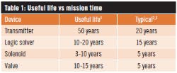
Mission time is loosely related to the useful life of the device. The useful life is typically the duration of the flat portion of the device’s “bathtub curve” between the infant mortality stage and the wearout stage of the device. So, MT should be less than or equal to the useful life of the device. Mission time selection is a function of the manufacturer’s specified useful life, expected process service stresses, and ambient condition stresses. Typical values for mission time are given in Table 1. At the end of the mission time, a device should be evaluated for replacement or rebuilt based on local maintenance experience.
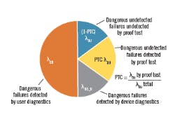
As we can see in Equation 3, the reliability clock for dangerous failure modes tested by the proof test resets (PFDavg) is zeroed at the end of the proof test interval. The reliability clock for failure modes not tested during proof test continues to accumulate PFDavg over the full length of the mission time, then the reliability clock resets if the device is replaced (new condition) or rebuilt (good as new) (Figure 2).
Figure 2: The reliability clock for dangerous failure modes tested by the proof test results (PFDavg is zeroed) at the end of the proof test interval. The reliability clock for failure modes not tested during proof test continues to accumulate PFDavg over the full length of the mission time, then the reliability clock resets if the device is replaced (new condition) or rebuilt (good as new).
Equations 2 and 3 are mathematical models used to calculate PFDavg to determine the SIL level to satisfy the requirements of IEC 61511. They are one of the engineering tools that help SIS engineers design a reliable SIS. Including the PTC in your SIL verification calculation will negatively affect the PFDavg based on what PTC values and mission time are used. If you compensate for the PTC by including the proof test coverage, you're potentially making your PFDavg more “accurate,” but is your SIS more reliable? Essentially, including the PTC in the calculation is recognizing that PTC must be evaluated for each safety function, and must be improved so it doesn't significantly affect the PFDavg calculation.
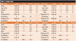
Four example, cases of complete safety instrumented functions with typical PTC and mission time values are provided in Table 2.
We can also look at Equation 3 to see when the lack of PTC starts to dominate the PFDavg (when (1-PTC) PFDavgMT is greater than PTC x PFDavgTI) as a measure of importance. We can rearrange Equation 3 by placing the two parts of the equation greater than or equal to determine when the lack of proof test coverage (1-PTC) becomes dominant:
PTC x ½ x λDU x TI ≤ (1-PTC) x ½ x λDU x MT (4)
(1-PTC) x MT ≥ PTC x TI (5)
MT ≥ x TI (6)
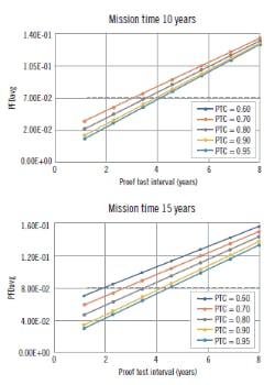
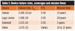
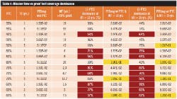
Table 3 provides the failure rates, PTC and mission time for the example safety instrumented function shown in Table 4 and Figure 3. The sensor, logic solver and solenoid have fixed PTC and mission times, and the logic solver proof test interval is fixed at five years. In the examples in Table 4 and Figure 3, only the valve PTC and mission time are allowed to vary.
In Table 4, it should be obvious that the “lack of proof test coverage” part of the PFDavg equation can begin to dominate the PFDavg calculation at lower PTC. The lower the PTC and the shorter the proof test interval, the quicker the (1-PTC) portion becomes dominant (more than 50% of the calculation). This indicates that increasing the PTC is a primary means of improving the reliability of the safety function. The PFDavg has problems when the proof test interval approaches five years and the mission time approaches 15 years.
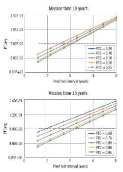
Figure 4 plots the PFDavg vs test interval for various PTC. It's obvious that, for the chosen typical cases, we can exceed the limit for SIL 1 when we start to exceed about a three- to four-year proof test interval. This reinforces the need to increase the PTC as high as is reasonably possible to ensure we don't have untested failure modes hanging around. Even if your SIL limit is achieved with low PTC, it doesn't mean you should ignore the PTC.
Figure 3: Plotting the Table 4 data for a valve PTC at mission times of 10 and 15 years, it is obvious that we can exceed the limit for SIL 1 when we start to exceed about a three- to four-year proof test interval. This reinforces the need to consider proof test coverage and increase the PTC until it is as high as reasonably possible to ensure that we do not have untested failure modes.
How can we raise PTC?
Proof test coverage comes from two primary sources: the manufacturer/approval agency and user analysis. The manufacturer or approval agency’s PTC is typically generated as part of a failure modes effects and diagnostic analysis (FMEDA). In the FMEDA, PTC is typically assigned to each identified dangerous failure mode (e.g., 0, 60%, 80%, 90%, 99%) and then summed up as part of the FMEDA analysis. This method can identify dangerous failure modes that lack significant PTC, but it can also result in no clear means to improve coverage if the PTC percentage can't be easily broken down and addressed (e.g., a number of small PTC adding over a large number of dangerous failure modes).
Users should ask the manufacturer for a breakdown of dangerous failure modes not fully covered by FMEDA’s recommended proof test procedure. Even the recommended proof test procedure can be improved to increase PTC, and some knowledge of dangerous failure modes that they consider not testing can go a long way.
The manufacturer’s PTC doesn't include the local plant and process conditions, and it's up to the user to analyze their system’s effect on the PTC. Essentially, the overall proof test coverage is the sum of the devices PTC plus the user's contribution to the PTC. If you have a low PTC, there is something wrong with the proof test procedures.
One concern with the manufacturer/approval agency’s number is whether the manufacturer has the capability to test for dangerous failures. If not, users could potentially receive a device with the failure mode already active and waiting for the right conditions. The user proof test procedure wouldn't catch the failure at installation.
There are typically two recommended proof test procedures in the FMEDA: a comprehensive proof test procedure and a partial proof test procedure. The partial proof test procedure typically allows the user to improve the PFDavg if it's done more often than the main proof test, or to extend the proof test interval. However, it doesn’t help you improve your PTC because you're just testing known “proof testable” failure modes more often to improve your PFDavg. Using the partial proof test to compensate for the lack of PTC is bad engineering practice.
User proof test coverage
In many cases, the user’s proof test procedure and testing practices can have a bigger effect on the PTC. The user proof test coverage generally starts with the user performing a FMEDA/FMEA on their SIS to identify all the dangerous system failure modes (random, non-random and systematic). All the dangerous failure modes should be evaluated for coverage by proof tests or by user diagnostics. Doing a FMEDA/FMEA of your SIS as part of your design is good engineering practice, and can be of benefit in detecting unknown failure modes and weak spots in the design. If you don’t purchase certified equipment with a PTC provided, it is up to you to determine the PTC of the SIS devices.
Even with the manufacturer’s PTC %, without further information from the manufacturer, reducing the PTC can be a matter of speculation of potential untestable dangerous failure modes. As a result, since we don’t have any information on the internal dangerous failure modes, the user must black-box-model the device. If information isn't available from the manufacturer on what the significant, untestable, dangerous failure modes are, you may want to consider selecting a different manufacturer.
Plant history of dangerous failures can be helpful, and unusual failures should be flagged as near-misses, analyzed to determine the root cause, and documented. One positive note is that once it’s done, 80% of the work is reusable when considering a different device’s PTC.
The FMEDA/FMEA should cover the whole safety function from end to end. It should also include an analysis of potential systematic failure modes, non-random failure modes (pluggage, erosion, corrosion, stickage, etc.), and an analysis of the proof test procedure’s coverage when not testing at operational conditions. If the proof test procedure is performed at ambient conditions when the process is down, consideration should be made as to how to compensate for not testing at operational conditions. The FMEDA/FMEA may result in additional coverage in the proof test procedure, additional user diagnostics, redundancy, procedural compensations to improve the PTC, and/or design revision.
One of the user areas for analyzing PTC involves testing for non-random dangerous failure modes (e.g., degradation failure modes). Examples of these are impulse line pluggage, valve erosion, valve corrosion and valve sticking. All of these are a function of time, process and ambient conditions. Since the PFDavg calculations assume that the dangerous failure rate is constant, this introduces an error. There is a need to have a new failure model to cover both the random and non-random failure modes (Reference 3). Users must consider these degradation failure modes when performing their FMEDA/FMEA.
The analysis of the user-written proof test procedure should include evaluation of test steps or actions that can facilitate human errors by the maintenance technician. While the failure of the written proof test procedure to cover all the dangerous failure modes (systematic failure by commission, omission or error) can be a problem, so can failure of the technician to perform the test procedure properly due to lack of resources, complicated test procedure (too long, too hard, too confusing, etc.), or human error (error is facilitated by procedure, lack of training, test equipment error, incompetence, laziness, etc.). Operational and maintenance discipline are important concerns in SIS testing. The best practice is to have a procedure for evaluating proof test procedures, use it to improve your test procedures, and continuously improve your proof test practices.
A walkthrough review with the technicians should be performed to determine how the test procedure flows, where it's complicated, where it's unclear, etc. A job safety analysis (JSA) should be done to ensure safe performance of the proof test. All test procedures should have a step signoff for the technician performing the work, and double-check and signoff if necessary.
Once we've completed the FMEDA/FMEA and identified all the tested and untested-by-proof-test dangerous failure modes, determining the PTC becomes an issue of how to allocate the PTC. Many times, the decision is a qualitative estimate based on values floating around in industry, user-determined values, or values based on the analyst’s experience. The percent coverage is commonly, simply an educated guess by the analyst because there's no recognized means to easily calculate PTC. Some users and analysts assign coverage for specific proof testing actions in a checklist, then add them up to get the PTC. An example of this can be found in Reference 1, which is given only as an example as the selected values may be different for different people or sites. Quantifying systematic failures that affect the PTC because they're not random can be difficult, and trying to add them to random failures can be like adding apples and oranges. Systematic failures should be minimized in the proof test process, so they don't significantly contribute to the unreliability of the SIS. Testing should be done for identified random and non-random failures. Non-random failures such as erosion, corrosion and pluggage typically require inspection.
Dealing with PTC problems
It's common practice when there's a problem achieving the desired SIL to improve the PFDavg by decreasing the proof test interval or performing online partial tests. If your SIL level is in trouble because your PTC is too low, decreasing the test interval or applying partial testing of known failure modes can bring the SIL level back under control, but you won't resolve the underlying problem of lack of PTC. The key question is, is your SIS more reliable when you do this? If the safety function has a PTC of 90%, this means that 10% of the dangerous failure modes will not be tested over the mission time, which could be several proof test intervals. Would you like to operate 24/7 with 10% of your safety functions not verifiable? I can guess what the operator’s answer to this question would be.
Reducing the mission time will improve the PFDavg, but does not address the primary problem of lack of proof test coverage. It also requires us to replace or rebuild the device sooner and before it reaches the end of the useful life, which represents an undesirable cost.
If you don’t know all the dangerous failure modes, ask the manufacturer/approval agency what they are; do a FMEDA/FMEA to determine what local conditions, design, procedures and practices contribute to PTC; and systematically reduce untested dangerous failure modes to an acceptable level (typically greater than 95%). Careful selection of instrumentation with high PTC, with advanced diagnostics, automatic online proof test, etc., can reduce the analysis load to determine PTC and result in a more reliable SIS. Doing a FMEDA/FMEA on all your safety instrumented functions is good engineering practice, and can detect unrecognized dangerous failure modes and weaknesses that should be corrected by the design, how well your dangerous failure modes are being tested, or user diagnostics.
PTC is an important parameter to consider in the reliable design of SIS systems. It's not sufficient to just plug it into the PFDavg calculation, make your SIL, and go on, happy as a clam.
[I want to thank Erik Mathiason, Jessica Lo, and Nicholas Wienhold of Emerson for an excellent discussion, and Steve Gandy of exida for additional information on the subject.]
References:
- “Proof Test Procedure Effectiveness on Safety Instrumented Systems,” Mohamed Abdelrhafour, Naresh Bajaj, Stephane Boily, 2012 Safety Control Systems Conference.
- “Are Your Safety Instrumented Systems Proof Tests Effective?,” ValveMagazine, Loren Stewart, June 2017.
- “Novel Model of Proof Test Coverage Factor,” György Baradits, János Madár, János Abonyi, 10th International Symposium of Hungarian Researchers on Computational Intelligence and Informatics.
Frequent contributor William (Bill) Mostia, Jr., P.E., principal, WLM Engineering, can be reached at [email protected].
Latest from Safety Instrumented Systems

Leaders relevant to this article:
