Why and how to use ultrasonic flowmeters for flare flow metering

Accurate flare flow metering is important to account for production and energy loss, closing the gaps in the plant mass balance, and in reducing emissions and protecting the environment.
Clamp-on ultrasonic flowmeters can't measure low-pressure flared gas in a metallic pipe because the flared gas has lower acoustic impedence than metallic pipes. This causes the acoustic signal to travel in the pipe and not to the second transducer across the pipe.
To address this limitation, there are two solutions. One option is to increase the flared gas pressure, which is difficult to accomplish. The other is to install a clamp-on flowmeter on a nonmetallic pipe. This will lower the acoustic impedence of the pipe and increase the possibility of acoustic signals traveling across the pipe and measuring the flow. Using a nonmetallic pipe in the flare header is also a challenging option and will require a very comprehensive assessment before implementation.
Existing industry regulations and standards provide helpful guidelines by defining the acceptable accuracy limits for flare flowmeters. The challenge has always been how to reveal the flowmeter inaccuracy and minimize errors in flare flow measurement. We've found practical tools to properly select, configure, install, test and maintain flowmeters in flare applications, and how to determine the flaring source using the built-in features provided by these flowmeter technologies.
Each of the different flowmeters used for flare applications has limitations. For example, differential pressure (DP) flowmeters such as orifice plates and pitot tubes are sensitive to fouling and composition changes, and will require frequent calibration. Conventional thermal flowmeters are also sensitive to fouling, liquid and composition changes, and will require frequent calibration unless they have automatic composition measurement and correction. Vortex flowmeters also have limitations in sensitivity to fouling and liquid, maximum flow capacity and maintenance difficulties.
An experiment (Table I) was carried out to demonstrate the possible errors in flare flow measurement using different types of flowmeters with different gas compositions. Because of the accuracies demonstrated in Table I and the above considerations, this article focuses on the use of ultrasonic flowmeters for flare applications.
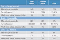
*The approximate measurement error under constant flow conditions when using a fixed composition of 1% CO2, 0.9% H2S, 97% methane, 1% ethane and 0.1% propane and the flare composition changes to:
Case 1: 0.53% CO2, 0.47% H2S, 51.08% methane, 0.53% ethane, 47.39% propane
Case 2: 0.4% CO2, 0.36% H2S, 38.8% methane, 0.4% ethane 0.04% propane, 60% hydrogen
Case 3: 12% CO2, 0.8% H2S, 86.22% methane, 0.89% ethane, 0.09% propane
Source: API MPMS 14.10
Flare flowmeter challenges
Flare applications introduce many challenges on flow measurement and flowmeters, the major ones being:
- Flare can have a very low flow (0.01 m/sec) and a low pressure drop across the meter (typically 0.5 psig is required).
- The flow can be non-axial and asymmetric. Laminar-turbulent transition flow introduces inaccuracy, and stratification (by sun or wind) can happen and affect the flow profile. Pulsating flow is also possible as the gas entry to the flare header is not continuous.
- High flow may cause low signal-to-noise ratio and probably liquid carry-over. High CO2, H2S, N2 and H2 can cause attenuation to the signal.
- Flare flow has a large turndown (2,000-4,000:1) and the gas composition is variable.
- Primary flow elements have uncertainties due to electronics drift, metrological (pipe diameter, alignment) and process buildup. Secondary instruments (temperature and pressure) have uncertainty due to electronics drift, mounting location and process buildup.
- The application might require a dual-path ultrasonic flowmeter (i.e., two sets of transducers) to either improve accuracy, cover very low flow conditions, or reduce the straight piping requirement.
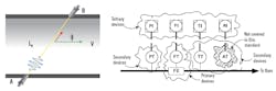
Figure 1: Ultrasonic flowmeters determine the flow velocity by measuring the difference in the travel time for a pulse moving from one transducer at one side of the pipe to another one at the other side and vice versa. Secondary instruments for pressure and temperature are required to calculate the volumetric flow at standard conditions. Source: API MPMS 14.10, SIO 17089-2
Ultrasonic principle of operation
Ultrasonic flowmeters (UFM) can be either insertion or cross-pipe. Both types are installed as single- or dual-path. These flowmeters (Figure 1) determine the flow velocity and speed of sound by measuring the difference in the travel time (tab - tba) for a pulse moving from one transducer at one side of the pipe to another one at the other side (tab) and vice versa (tba). The transducers are inserted through the pipe wall, either by hot tapping or as an inline flowmeter (installed on a spool pipe). The flowmeter calculates the flared gas velocity (V), volumetric flow at operating conditions (Qact) and volumetric flow at standard conditions (Qstd).
Sound velocity (C) is also calculated by this flowmeter. The value of sound velocity is used to estimate the molecular weight (MW) of the flare gas mixture. A mathematical or graphical correlation is experimentally extracted by testing many gas mixtures and defining their sound velocity and MW relationship. MW measurement helps in calculating the density and therefore the mass flow.
Secondary instruments for pressure and temperature are required to calculate the volumetric flow at standard conditions. The setup of these secondary instruments is shown in Figure 1 or as advised by the flowmeter's manufacturer.
Referring to Figure 1, the main equations are:
- V = [L /(2cosØ)] x [1/tab-1/tba]
- C = [L/2] x [1/tab+1/tba]
- Qact = V x pipe area
- Qstd = Qact x P/Ps x Ts/T
Where:
- V: flow velocity
- C: sound velocity
- Qact: volumetric flow at actual flow conditions
- Qstd: volumetric flow at standard flow conditions
- L: distance between transducers
- tab: time for signal travel from transducer a to transducer b (and vice versa for tba)
- T, P: operating temperature, pressure
- Ts, Ps: standard temperature, pressure
Specification and testing
ISO 17089-2 and BS 7965 define the required flowmeter uncertainty in flare application to be ≤10% for the flow above a certain minimum limit. This uncertainty can increase by 5% due to flowmeter installation effects. The flare flowmeter needs to be tested at the factory or at a third-party calibration shop. The main testing requirements are:
- Air is usually the testing media. A Reynolds number is used to account for differences in densities (between air and flared gas composition).
- Expansion of the flowmeter shall be considered in high velocity.
- Testing shall cover 0.03 m/s to the maximum design velocity. The flowmeter shall be tested at velocities 0.03, 0.15, 0.30, 0.61, 1.5, 3.0, 6.1, 15, 30 and 15 m/s increments up to the maximum operating velocity.
- The flowmeter shall be tested with the same pipe size and upstream/downstream straight piping.
- Pressure transmitter accuracy shall be maximum ±0.67 kpa.
- Temperature transmitter accuracy shall be maximum ±2 °C.
- The testing facility shall be traceable to NIST or equivalent national or international standard, and shall be accredited by ISO/IEC 17025.
- The factory and testing facility shall provide all the testing data and records of the installation, configuration and diagnostics data at the test bench.
- The manufacturer shall provide the flowmeter uncertainty and the installation effects.
- Testing shall be done at a low pressure and at ramping up and down.
Installation and commissioning
Requirements stated in API MPMS 14.10 and 22.3, ISO 17089-2 and BS 7965 will help users reach an accurate flare flow measurement. The major points to follow are:
- Manufacturer or manufacturer-certified entity shall be responsible to install and commission the flare flowmeter and all secondary instruments. This will eliminate critical problems, like transducer misalignment.
- The end user shall decide early on the installation approach (i.e., hot tapping, cold tapping or a complete spool piece). Definitely, the last option is the best option as it will eliminate all installation errors.
- Transducers shall be retractable to allow online removal for testing and replacement.
- Recommended piping straight run is generally 20 diameters (20D) upstream and 10D downstream. This requirement can be relaxed based on the specific flowmeter installation and manufacturer recommendations, which must be verified.
- The end user shall consider accessibility for flowmeter maintenance and gas manual or automatic sampling.
- Pressure and temperature sensor mounting locations shall follow the flowmeter manufacturer's recommendations.
- Vibration shall be avoided by selecting the right location for the flowmeter and its associated panel.
- Any control valve with noise attenuation or fittings up or downstream shall be checked, as this can produce interference with the transducer pulses.
- The installation shall avoid liquid accumulation.
- Rapid pressurization or depressurization when removing or installing transducers shall be avoided.
- Manufacturer shall provide the accuracy impact when replacing any part or software of the flowmeter system.
- The hardware serial numbers, firmware and testing shall be submitted by the vendor.
- All data and software configuration in electronics are saved as a backup. After commissioning, management of change (MOC) is required.
Field verification
To verify the reading of an installed ultrasonic flare flowmeter, there are many techniques. The steps and tools below can be used:
- The flowmeter manufacturer shall be requested to provide a written procedure for functionality testing and verification, inspection intervals and dimensional verification. Also, uncertainties and speed of sound calculations shall be provided.
- Wall thickness, inclination angle of transducers, length of acoustic path, the pipe internal diameter and pipe cleanness shall be verified.
- Installed meter specifications and current operating conditions shall be checked to match the flowmeter's specification sheets and drawings.
- The installed flowmeter configuration and serial number shall be verified with the manufacturer requirements.
- Straight piping and installation of the meter, pressure and temperature transmitters shall be verified.
- Wiring shall be inspected for signs of moisture or physical damage.
- Performance of the flowmeter using the same transducers model and the same installation setup at a calibration shop can be checked. This is to verify the accuracy of the installed flowmeter, considering the same straight piping and mounting of the current field installation.
- The ultrasonic flowmeter reading can be verified using a secondary device such as:
- A second insertion flowmeter (such as a pitot tube).
- Optical method (laser doppler anemometer tracer), which requires a steady velocity.
- Tracer dilution technique: injecting a gas (like SF6 or helium) and measuring the flow rate increase using a secondary flowmeter.
- Radioactive tracer: introducing a gaseous radioactive tracer and inserting two detectors to detect the passage (based on transit time). BS-5857-2 can be referenced for details.
- The transducers and the electronics can be verified using a zero flow box. This will provide zero calibration of transducers, and will also check speed of sound measurement for air compared to the estimated value (performed by the manufacturer software). Also, zero testing can be done for the electronics and cabling using dummy transducers and checking the signals.
- Absolute speed of sound (C) comparison, like injecting N2 and determining C.
- Verification of the ultrasonic flowmeter can be also done by taking a sample of the flared gas and measuring SOS, and then comparing the measured value to the flowmeter estimated SOS. Difference shall be less than 0.25%.
- Another verification tool is comparing C and the velocity reading of one path, and comparing it to the second path. This is only applicable for dual path measurement (i.e., when two sets of transducers are installed).
- Flaring volume could be estimated by conducting mass balance or using process simulation, and the result can be compared to the flowmeter reading.
- Computational fluid dynamics (CFD). This is a modeling and verification technique, which is a cost-effective solution and helps to reveal installation errors. Also, it provides a correction for the flow profile and the missing straight piping run. The flow is modelled in 3-D coordinates considering turbulence and wall roughness. Manufacturers of flare flowmeters or some flow calibration labs can provide this service.
Observing flared gas and not being able to determine which operating flare branch it's coming from is very frustrating for operating facilities. In many circumstances, the source of the flared gas is a leaking valve. However, identifying which valve and from which operating unit is difficult and time consuming.
An ultrasonic flowmeter offers a solution to this problem because the most valuable advantage of the technology is the sound velocity measurement. There's a determined sound velocity value for every type of gas and for every mixture of gases. Knowing the sound velocity will determine the molecular weight and composition of the flared gas. Knowing the composition will help the operating facility identify the potential sources of flaring. This is a unique feature of ultrasonic flowmeters.
Online performance monitoring
Ultrasonic flowmeters have the advantage of providing online diagnostics. Diagnostics can be used to check the health, performance and the accuracy of the flowmeter without the need to remove and physically check, calibrate or replace any part. Once the flowmeter is proven to be correctly selected, installed and commissioned, diagnostic parameters can be collected and used as a baseline for future online performance monitoring.
The flare flowmeter manufacturer shall be requested to provide detailed diagnostics parameters along with their acceptable limits. Having these diagnostics parameters in the local display and also reflected in the remote workstation (i.e. distributed control system) is crucial for online performance monitoring. The main diagnostics parameters to be displayed and monitored are:
- System diagnostics: Transducers and electronics functionality check, flow profile. This diagnostic parameter helps with the recalibration decision.
- Speed of sound (C): The measured C and the actual C can be compared to check the health of the flowmeter. Actual C is calculated using a gas sample and the flowmeter manufacturer software. Also, compare the initial flowmeter C reading and the current C.
- Signal strength/quality indicator: Signal-to-noise ratio (SNR) indicates the quality of ultrasonic signals. Distribution of SNR among transducers might indicate a source of a problem such as noise.
- Automatic gain control (AGC) level: As meter performance deteriorates, AGC level increases and a fault happens.
- Flow profile: A change in flow profile indicates viscosity changes and/or changes to pipe wall roughness.
- Axial velocity through the flowmeter.
- Meter performance: The ratio of transducers good pulses received to rejected pulses received. As the flow rate increases, meter performance decreases. Performance also decreases with a decrease in pressure.
- Temperature: Can indicate stratification in the gas flow.
Following the above steps will assist end users in evaluating their installed flare flowmeters and could also result in modifying or even replacing existing flowmeters to fix the system performance and installation errors.
About the author:
Fawaz AlSahan, engineering specialist and chairman of instrumentaiton standards at Saudi Aramco, is a Certified Engineering Consultant (SCE) and a Certified Automation Professional (ISA) with more than 19 years of experience. He can be reached at [email protected].
References:
- APIMPMCH14.10, Metering flare application
- APIMPMCH22.3, Test protocol for flare gas metering
- BS7965, Guide to the selection, installation, operation and calibration of diagonal path transit time ultrasonic flowmeters for industrial gas applications (including flare gas)
- How do you measure flare gas effectively with clamp-on ultrasonic flowmeters? http://www.siemens.com/
- ISO 17089-2, Measurement of fluid flow in closed conduits—ultrasonic meters for gas
- Saudi Aramco best practice (SABP-J-202)—flowmeter for flare application
