Diagnostics effects on SILs and spurious trips

This article describes how reliability data validation (RDV) should be applied to properly determine if safety system devices are individually capable of satisfying the target safety integrity level (SIL) rating, and verify if the whole safety system implementation performs according to design.
Reliability data on safety devices is very important for calculating reliability indexes including safe failure fraction (SFF), average probability of failure on demand (PFDavg), average dangerous frequency of failure (PFHavg), spurious trip rate (STR), mean time to fail spuriously (MTTFs), mean time to fail dangerously (MTTFd), etc. (See “Acronyms alphabetized” sidebar.) The indexes are used to verify if a safety device or safety instrumented function/instrument protective function (SIF/IPF) is capable of satisfying a target SIL rating.
Common engineering errors
Sometimes, a SIF/IPF implementation doesn’t consider all the potential individual safety device failures, as well as combined failures among them, despite a certificate that indicates installation satisfies the target SIL rating. Or, using traditional black box calculation tools leads engineering to focus on manipulating software to obtain acceptable results without question, instead of analyzing data and results according to the safety requirements specification (SRS) and the way the SIF devices were implemented.
For example, a safety device has diagnostics to reveal detected failures, and this device is selected to be included in a SIF/IPF, but the device implementation doesn’t communicate to the safety/control system when a detected failure occurs, even though its fault detection capabilities (diagnostics) are working properly. In this case, the operators never know what’s happening, even though the device is capable of warning them. Diagnostics are very valuable for allowing a safety device to help reach a higher SIL classification, but the implementation didn’t consider the use of diagnostics, and therefore, the SIL requirement of the SIF/IPF implementation isn't satisfied.(References 6 and 7 give examples of RDV applications.)
IEC treatment of diagnostics
The terms in the sidebar, “Attributes for failure classification,” are formalized in the sidebar, “IEC 61508 elements,” and organized in the IEC 61508 failure mode diagram shown in Figure 1.
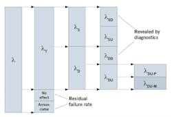
Figure 1: The total failure rate λ includes the fraction considered in reliability indexes (λT), which can be further divided into safe vs dangerous (λS vs λD); safe detected (λSD), safe undetected (λSU), dangerous detected (λDD) and dangerous undetected (λDU). The λDU fraction may be revealed by proof test (λDU-P) or by maintenance (λDU-M).
The IEC 61508 failure rate model states that if a SIF/IPF device includes fault detection capabilities, (diagnostics), then the “safe” and “dangerous” failure rates have a portion for failures that can be detected by diagnostics (SD and DD), and a portion that can't (SU and DU). Detected failures distribution has positive credit in the SIL verification, making it easier to satisfy the SIF/IPF implementation safety integrity targets, constraints and other requirements.
However, even if a related SIF/IPF device includes diagnostics, if the diagnostics aren't used or are not considered in the SIF/IPF implementation/installation, then no credit for diagnostics shall be taken in the SIL verification process.
For example, Table 1 shows the failure rate data for a SIF/IPF device in failures in time (FIT). It indicates that the device includes fault detection capabilities (diagnostics), so the device is capable of revealing detected safe (SD) and dangerous (DD) failures. But, if the SIF/IPF implementation/Installation doesn’t use or take advantage of the device diagnostics, those diagnostics shall not have credit in the SIL verification process. In this case, data in Table 2 shall be used for SIL verification, instead of data in Table 1.
- Fail safe: Failure that causes a target system to move from the normal to the safe state. Typically identified as a spurious trip.
- Fail dangerous: Failure that prevents a target system from successfully performing on demand. In other words, when a hazard occurs, the target system can't perform its automatic protection function and it will remain in the normal state.
- Fail detected: Failure in a target system that can be detected by an automatic diagnostic test. This test implementation is capable of notifying both a safety/control system and operator. Any automatic diagnostic test execution frequency must be higher than a proof test execution frequency.
- Fail undetected: Failure that can't be detected in a target system by an automatic diagnostic test. Notification capability doesn't exist. Only an operator intervention, proof test or maintenance can reveal the failure.
- No effect: Failure that has no effect on a target system automatic protection function. In other words, failure that doesn't prevent a target system to perform its automatic protection function and doesn't initiate a spurious trip.
- Annunciation: Failure that has no effect on a target system automatic protection function, but the target system automatic diagnostic test and/or notification capabilities have stopped working. In other words, this failure has no impact on safety, but fault detection capabilities (diagnostics) or notification capabilities will not work.
Table 2 is the RDV result, which indicates that even though the device is capable of using diagnostics, the benefits from such diagnostics don't perform in the SIF/IPF implementation/installation.
Because the maximum SIL rating that a device can claim is determined by SFF (reference 4, section 3.6.15), after adjustment according to Table 2, the referred SIF/IPF device may not satisfy the target SIL rating. The change in a SIF/IPF device SFF will affect the SIF’s SIL rating, because the maximum SIL rating a SIF/IPF can claim is determined by “Route 1H (or 2H)” (reference 3, section 7.4.4).
Internal vs external diagnostics
Nowadays, fault detection capabilities (diagnostics) can be provided by the safety device manufacturer as part of the safety device itself, or in the SIF/IPF design by external devices or systems that aren't required to make a SIF/IPF perform as it was designed.
In the following discussion, the logic solver must be able to recognize a diagnosed fault, execute additional actions and notify the operator. Otherwise, all the following proposed ways to handle fault detection capabilities (diagnostics) are useless, diagnostics have no credit for SIL verification and the above transition from Table 1 to Table 2 applies.
Modern transmitters can include diagnostics, and their results can be communicated to downstream safety devices or a logic solver via NAMUR NE 43 or a NAMUR sensor (EN-60947-5-6:2000 and IEC-60947-5-6:1999).
Some other sensors, for example, fire and gas sensors with external power supply, commonly use a 1.0-2.0 mA current level to indicate an internally detected fault. In those cases, the logic solver must be able to read those current levels and be programmed to interpret those levels as a diagnostic fault. Proper implementation shall apply to guarantee that a transitioning current level doesn’t cause a spurious trip.
A typical example of diagnostics from external device is a valve positioner in an actuator/valve. It's a fact that a mechanical device doesn’t include fault detection capabilities (diagnostics) unless it’s combined with an electronic device that can monitor the performance of the mechanical device.

This is the case for both the actuator and the valve. Both are pure mechanical devices with no possibility of providing diagnostics by themselves. But, a positioner can monitor the actuator/valve arrangement’s condition and performance. The diagnostics results can be transmitted to a control/safety system for automatic actions, or for operator warning in the related SIF/IPF. (For more examples with SOVs, see reference 6.)
When the above uses of diagnostics don't apply, the safety device with diagnostics can be connected to an asset management system (AMS) to provide automatic warnings to a control/safety system about the related SIF/IPF. (References 6 and 7 offer practical application examples.)
In any case, for diagnostic implementations like these to be reliable, the diagnostic frequency must be greater than the related proof test (TI) period. For example, if TI for a safety device is six months and the related diagnostics are executed via AMS/HART every week, the implementation looks OK. If TI is six months and the related diagnostics are executed via AMS/HART every eight months, the diagnostic implementation shall not get credit for safety purposes and SIL verification.
| FIT: Failures in time (per billion device-hours) | PFHvg: Average dangerous frequency of failure |
| IPF: Instrument protective function, same as SIF | RDV: Reliability data validation |
| MTTFd: Mean time to fail dangerously | SFF: Safe failure fraction |
| MTTFs: Mean time to fail spuriously | SRS: Safety requirements specification |
| MTTR: Mean time to repair | SIL: Safety integrity level |
| PFDavg: Average probability of failure on demand | SIF: Safety instrumented function, same as IPF |
| STR: Spurious trip rate |
Spurious trips and SIL ratings
Strictly speaking, the spurious trip rate (STR) calculation for a SIF/IPF only depends on SIF/IPF decision logics where the SIF/IPF device is used (use MTTR in calculation), and the SIF/IPF devices’ safe detected (SD) and safe undetected (SU) failure rate values. Nevertheless, if fault detection capabilities (diagnostics) are used in the SIF/IPF implementation, then one of the following considerations may apply. (All rely on the use of diagnostics—without them, none would have the maximum SIL rating that can be claimed by SFF, or even make sense.)
Consideration 1: By default, when a safe detected (SD) failure occurs in a SIF/IPF device, the operator is notified, then the device condition shall change to initiate a SIF/IPF spurious trip. If the SIF/IPF device fault detection capabilities (diagnostics) are used to detect SD failures in a device located in a SIF/IPF input channel, the SIF/IPF implementation can stop the spurious trip and still warn the operator. Technically, no spurious trip occurred.
Consequently, the SIF/IPF device safe detected (SD) failure rate (lSD or LdSD) isn't used in the spurious trip rate (STR) calculation, but it is included in the SIL rating calculation (because it behaves as DD). Then, reliability data from Table 1 shall be adjusted as shown in Table 3 for the SIL verification calculation.
In summary, for consideration 1:
- Device performs to avoid spurious trips from SD failures (logic solver shall recognize diagnostic fault result),
- Decreases spurious trip rate (STR),
- No effect on device maximum SIL rating to claim, and
- Increases device contribution on SIF/IPF SIL rating.
By design, maintenance shall have a chance of MTTR time to repair detected SD failures, otherwise safety shall apply. This means that If this consideration applies in the SIF/IPF design/implementation, when a SD failure occurs in the referred SIF/IPF device, SIF/IPF implementation shall stop the spurious trip, but a demand shall be initiated to set the SIF/IPF FSE in the safe state after MTTR time expires.
- Total failure rate (TFR): Average frequency of failure, or chance of a single component, device, arrangement or system, to fail within a period of time.
- Safe detected (SD) failure rate: Portion of the TFR where a single component, device, arrangement or system will fail safe, and this condition is fail detected.
- Safe undetected (SU) failure rate: Portion of the TFR where a single component, device, arrangement or system will fail safe, but this condition is not fail detected.
- Dangerous detected (DD) failure rate: Portion of the TFR where a single component, device, arrangement or system will fail dangerous, and this condition is fail detected.
- Dangerous undetected (DU) failure rate: Portion of the TFR where a single component, device, arrangement or system will fail dangerous, but this condition is not fail detected. DU failures can be detected by operator intervention, by proof test (if it can reveal the referred DU failure) or maintenance.
- Residual failure rate: Portion of the TFR that cannot be classified as SD, SU, DD or DU. Annunciation and "no effect" failures are included in residual failures.
- Dangerous undetected (DU-P) failure rate, revealed by proof test: When proof testing cannot reveal all DU failures, this is the portion of the DU failures where a single component, device, arrangement or system will fail dangerous, but the condition is not fail detected and can be revealed by proof test.
- Dangerous undetected (DU-M) failure rate, revealed by maintenance: When proof test cannot reveal all DU failures, this is the portion of the DU failures where a single component, device, arrangement or system will fail dangerous, but the condition is not fail detected and only maintenance can reveal the failure.
- Proof test effectiveness (Et) or proof test coverage (PTC): Et = PTC = (DU-P/DU), the fraction (0-100%) of the DU failure rate can be revealed by proof test, applicable when proof test is not capable of revealing all DU failures.
Consideration 2: By default, when a dangerous detected (DD) failure occurs, the operator is notified, and the normal operation continues. SIF/IPF will fail on demand. No spurious trip occurs.
At this point, SIF/IPF design/implementation has the following choices:
- Operator is notified and SIF/IPF waits forever until maintenance is applied to repair SIF/IPF device in failure. (Not recommended, as the target system isn't protected.)
- Allow operation to continue for MTTR time, and notify the operator. When MTTR expires, SIF/IPF implementation shall initiate a demand to set the SIF/IPF FSE in the safe state. Technically, no spurious trip occurs.
- SIF/IPF implementation shall initiate a demand at once when DD failure is detected, and the operator is notified. Technically, a spurious trip occurred.
In choice three, SIF/IPF implementation behavior for DD failures is the same default one as when a SD failure occurs (see Consideration 1). Consequently, assuming the referred SIF/IPF device reliability data is as shown in Table 1, SIF/IPF device dangerous detected (DD) failure rate (DD or LdDD) is in fact promoting a spurious trip, so it shall be used in the spurious trip rate (STR) calculation, but not in SIL verification. Then reliability data from Table 1 shall be adjusted as shown in Table 4.
In summary, for Consideration 2:
- No effect on device maximum SIL rating to claim,
- Device performance increases spurious trips (now DD failures can initiate a spurious trip), and
- Device contribution on SIF/IPF SIL rating is decreased.
Reference 7 gives practical application examples on SIF/IPF output channel.
Consideration 3: For safety devices located in the SIF/IPF input channel, when the logic solver is able to execute actions at the time when SD or DD failures occur in any input channel device, SIF/IPF design/implementation can take credit for the benefits from combining Consideration 1 and Consideration 2. Consequently, the SIF/IPF design/implementation can avoid spurious trips from detected failures, and reliability data from Table 1 shall be adjusted as shown in Table 3.
In summary, for Consideration 3:
- Device performs to avoid spurious trips from SD and DD failures (logic solver shall recognize diagnostic fault result),
- Spurious trip rate (STR) is decreased,
- No effect on device maximum SIL rating to claim, and
- Device contribution to SIF/IPF SIL rating is increased.
References 6 and 7 give application examples of Consideration 3.
About the author
Claudio Passarella, director-CEO, Liutaio Consulting and Engineering Services can be reached at [email protected].
References
- Liutaio – Functional Safety Services, 0418D10SD01 Abbreviations - Sample Document, Rev.01
- Liutaio – Functional Safety Services, 0418D10SD02 Glossary - Sample Document, Rev.01
- IEC 61508 Functional safety of electrical/electronic/programmable electronic safety-related Systems, Part 2: Requirements for electrical/electronic/programmable electronic safety related systems
- IEC 61508 Functional safety of electrical/electronic/programmable electronic safety-related Systems, Part 4: Definitions and abbreviations
- Exida position paper, IEC 61508 2010 Definitions Regarding Minimum Hardware Fault Tolerant / Architectural Constraints
- Liutaio – Functional Safety Services, Example 1 - Steam Turbine K-1122 – Conceptual SRS and SIL verification report
- Liutaio – Functional Safety Services, Example 2 – Letdown Station – Conceptual SRS and SIL verification report
