Differential pressure level in a purged tank

This column is moderated by Béla Lipták, automation and safety consultant and editor of the Instrument and Automation Engineers' Handbook (IAEH). If you have an automation-related question for this column, write to [email protected].
Q: When using a differential-pressure (DP) level transmitter, are the high and the low pressure ports reversed if the tank is purged with nitrogen? Purging is needed because the tank contains a hydrate inhibitor.
R. Revish
[email protected]
A: In all wet leg-type level installations, the top connection on the tank is connected to the high-pressure side of the DP cell, and the bottom one to the low-pressure side, because the wet leg is always full of liquid (a constant head pressure plus the pressure of the head space or nitrogen purge), while the hydrostatic head at the bottom connection varies and is always less than the one on the wet leg side (the level in the tank is changing, while the level in the wet leg is constant and always higher). Naturally, in such installations, the DP transmitter has to be reverse-acting.
This reminds me of the Fukushima accident, with which I was involved, and later wrote a book about how to fix its controls. During the accident, the water level reading showed the level rising when it was dropping because the temperature around the overheated reactor caused the condesate in the wet leg to boil off. The Fukushima installation is shown in Figure 1.
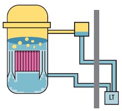
Figure 1: The arrangement of the level transmitter (LT) in the reactor vessel at Fukushima, according to Dr. Ritsuo Yoshioka, president, Japanese Functional Safety Laboratory.
In my correction of this level control loop, I added a second DP cell (∆PT in Figure 2) that is continuously detecting the height of the level in the wet leg (A in Figure 2). If, for any reason, the height of this reference leg is dropping, the amount of drop is added to the the output signal of the level transmitter (LT in Figure 2).
Naturally, in your application—if you’re sure that the wet leg will always be there and will always be of constant height—you don’t need the correction I made in Figure 2 for the Fukushima reactor. In your case, you can just reverse the pressure taps or use a reverse-acting transmitter.
Béla Lipták
[email protected]
A: It’s very difficult to help you with the minimal detail you provided. However, if we review some general details of level measurement, maybe you can understand some of the difficulties in using differential pressure to measure liquid level.
In Figure 3, the pressure at the top of the tank must be presented to the DP level transmitter (LT) through an impulse line. The impulse line is not empty. It may be filled with a non-corrosive fluid designed for this purpose, or it may be filled with condensate of the fluid in the tank being measured. For that reason, I labeled this tubing as “wet leg” in the drawing. Likewise, the pressure at the bottom of the tank is also presented to the LT via its impulse line (not labeled in the figure).
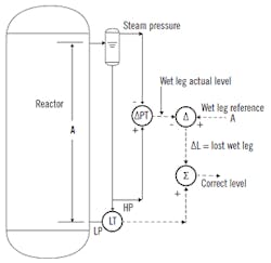
Figure 2: A second DP cell (ΔPT) continuously detects the height of the level in the wet leg (A). If the height of this reference leg is dropping, the amount of drop is added to the output signal of the level transmitter (LT).
We know the pressure due to the liquid level in the tank is higher at the point of measurement (D) than the pressure at the top of the tank (P1) in the drawing.
However, the LT sees the pressure at the top as the weight of the fluid in the wet leg plus P1, while the pressure at the bottom is the sum of the weight of the tank fluid (head) plus the weight of the fill fluid in the bottom pressure sample line plus P1.
From this analysis, you can see that the pressure at LT at the wet leg (top of tank) will actually be higher than the pressure at LT from the bottom of the tank. This is due to the pressure head from the wet leg. Many instrument mechanics are confused by this, and connect the top and bottom pressure taps in the reverse positions on the LT, which is what I would guess has happened in your case.
Since the only thing you're interested in is the level in the tank, even though the connections are reversed, the difference between the HP and LP taps will still be a correct measurement of liquid level. Sometimes we're just lucky.
For others, note that using a HART or Foundation fieldbus smart level transmitter will allow you to do a wet leg compensation when the DP appears to be negative because the LP is connected to the wet leg and the HP is connected to the bottom of the tank.
Dick Caro
[email protected]

Figure 3: Here, A is the measurement span; B is the distance of the minimum level above the connection; C is the distance from the high side connection to the top of the instrument connection and may be filled with fluid; and D is the actual liquid level above the transmitter (LT) low side. In wet leg applications, C is connected to the high side and D is connected to the low side of LT.
A: To measure level in a closed tank that's purged with nitrogen, you need to follow these steps.
- Determine the span of the measurement: high point minus low point (in meters, inches, feet, cm, etc.).
- Since you'll be using a purge that adds pressure onto the measurement element, you'll need to know the following: pressure (in bar, psig, etc.) and if the pressure will be constant or variable.
- Next, you'll need to define the type of connection on the tank—to know how the DP cell is to be connected (tubing, seals, wet leg, etc).
- Then, identify the location of the transmitter versus the datum or low level point of measurement of the tank (in meters, inches, feet, cm, etc.).
Depending on the location of the transmitter to the datum line, type of tank connection, etc., and with the formulas of the links below, it will be very clear why the low-pressure side may have a higher pressure causing a negative value.
It would appear that you have a differential pressure transmitter with a wet leg. That means that the low-pressure side is filled with liquid to the very top of the tank connection point. This wet leg will always have a pressure of the wet leg height multiplied by the density of the fill liquid plus the purge pressure on the top of the tank. This means the pressure will always be higher than the one being sensed on the lower connection, which will vary.
The easiest method to handle this is to interchange the connection points—then you'll be subtracting the level head from the wet leg head, giving a positive value. But be careful, since as the level drops, the value of the signal will increase.
Reference links:
- www.controlglobal.com/assets/wp_downloads/pdf/mma_070921_endress_liquidlevelpart1.pdf
- https://instrumentationtools.com/closed-tank-level-measurement-using-dp-transmitters
- www.emerson.com/documents/automation/technical-data-sheet-level-measurement-pressure-rosemount-en-74346.pdf
- www.ibiblio.org/kuphaldt/socratic/sinst/output/level.pdf
- https://automationforum.co/open-closed-level-measurement
- https://automationforum.in/t/what-is-lrv-and-urv-how-to-obtain-lrv-urv-for-level-measurment-using-differential-pressure-transmitter/2396
- https://instrumentationtools.com/open-and-closed-tank-level-calculations
Alex (Alejandro) Varga
[email protected]
