This column is moderated by Béla Lipták, automation and safety consultant and editor of the Instrument and Automation Engineers' Handbook (IAEH). If you have an automation-related question for this column, write to [email protected].
Q1: When vapor space condensation can occur, is a guided wave or non-contacting radar level detector the better choice?
A. Rahimi
[email protected]
A1: I'll start with a broader discussion of the radar (radio detection ranging) level measurement topic before answering your specific question.
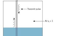
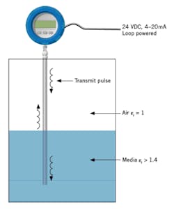
Figure 1: In guided-wave radar applications, the dielectric constant of the media measured must be greater than 1.4. In transition zones, (0-18 in. from top or bottom) readings can become nonlinear. In addition, foam or coating can cause error that gets worse with higher dielectric constant, extent and/or density of the foam or coating.
Guided wave radar (GWR) technology has been used for many decades, employed for such purposes as finding breaks in underground cables and in-wall cable installations of large buildings. GWR operates by launching low-amplitude, high-frequency pulses onto the waveguide, and then sequentially sampling the reflected signal amplitude. Typically, reflected pulse amplitudes are displayed on a calibrated time scale. In this way, cable impedance changes or, in this case, tank levels can be assessed (Figure 1).
Changes in the dielectric constant of the vapor space does cause errors. For example, if the temperature (and pressure) of steam in a vapor space increases, the dielectric constant also rises. This increase in vapor space dielectric causes a delay in the GWR signal propagation as it travels down the probe to the process medium. This signal propagation delay results in the liquid level appearing to be lower than it actually is. This error can be minimized by placing a mechanical target onto the probe within the vapor space, which produces a small signal reflection at that known and fixed location.
The phase difference sensor (PDS) is similar to GWR, except that it operates in the frequency domain rather than the time domain. PDS measures the level on the basis of changes in phase angle. It operates by sending a high frequency signal through parallel conductors at a fixed velocity until it's partially reflected by the stored material interface where the sensor impedance abruptly changes. The dielectric constant remains near unity, even if dust, vapor, condensate or foam are present, and therefore the signal injected into the sensor probe travels down to the material interface and back at a constant velocity.
In the case of most media, as the temperature increases, the dielectric constant decreases. Therefore, this inverse relationship requires that the level value detected be correspondingly corrected. Another source of errors in both GWR and PDS measurements is coating, if the media is high dielectric (e.g. water-based). The worst error source is a thick, high-dielectric coating that runs the full length of the probe.
There are two basic types of non-contacting radar level sensors: pulse type and frequency modulated carrier wave (FMCW) type. Both detect the time of flight from the sensor to the level in the tank. The pulse method is similar to sonar, where the time of the echo return is measured. They're similar to most ultrasonic sensors, except that the pulse units operate between 6 and 28 GHz, and not at utrasonic acoustic frequencies. These units are employed mostly for liquid level measurement and can't measure interface. Agitators, thick foams, window coating, condensation or splashing can cause problems. The antennas can have parabolic reflectors or differently shaped horns.
Most pulse radar detector suppliers have five or six models. They're designed for measuring liquid or solids levels, can have different measuring ranges, and housings with ambient or high temperature or pressure ratings. They can also be waterproof or equipped to handle hazardous or vaporous environments. Small antenna size, minimal or zero blank zone, and threaded process connections down to 1 in. are available.
In the more widely used and somewhat more expensive FMCW design, time of flight is tracked onto a carrier wave. The detector output is a frequency signal, which is the difference between the "send" and the reflected return signals. This difference is directly proportional to the time of flight and thus to the level. In general, radar gauges are often replacing ultrasonic detectors, but they still have problems in detecting foam and low-dielectric materials.
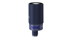
Non-contact radar gauges can be equipped with a polypropylene or PTFE “drop” antenna for use with condensing atmospheres and corrosive media. According to one supplier, this FMCW radar level transmitter provides accurate readings in closed tanks, open-air applications like rivers or dams, and even in fast moving processes.
So, coming back to your specific question, contacting gauges with a guide antenna are used more often when condensation is present, but non-contacting ones are also available.
Béla Lipták
[email protected]
Q2: I really admire your books on instrumentation, which focus on practical aspects of automation and control. Generally in my country, the facility to calibrate radar level transmitters (non-contact type) is not available. Can you suggest any alternative method (which can be used by maintenance personnel) for calibrating non-contact type radar level transmitters? Do the manufacturers of radar level transmitters give any guarantee that their units do not require periodic recalibration?
K V Ratnakar
[email protected]
A1: I assume you have a non-contact radar cone and not a wave-guide model. In that case, measure the actual distance from the cone to the zero level in your vessel. If it's a closed pressurized vessel, use the design engineer's internal vessel drawings or use the dimensions of the vessel itself to determine what and where 0% and 100% are on the vessel. Calibration can be as simple as entering these values directly as your z/100% calibration, or you might have to do a small calculation like maximum possible distance (tank depth) minus z measured distance equals zero distance, and maximum possible (tank depth) distance minus 100% measured distance equals 100% distance.
Also, keep in mind that radar measures distance, and vapor space measurement is the opposite of level. You therefore need to modify the local display to indicate level in mm or percent, as well as set up your output to be based on level, and not on distance after the calibration. The radar will then send out a 4mA signal when the tank is empty and 20mA when the tank is full, or when the level has reached the point where you have specified 100% to be.
Dick Caro
[email protected]
A2: Special considerations may be needed in applications where product can build-up or splash on the radar antenna. But in general, with no moving parts to lose tolerance, radar transmitters need very little maintenance. So, calibration should not be required for a well-designed (and properly applied) radar device, but if periodic proof-testing is desired, frame programs like PACTware can be used to periodically view and compare waveforms to gain confidence in the proper operation of installed radar instruments.
Advances in the diagnostic capability of radar devices now allow for saving reference curves, which makes comparing a waveform taken last year to one taken more recently very simple. Coverage may be increased by comparing these waveforms at two different levels in the vessel. In addition, configuration changes are typically very simple to accomplish remotely (via HART or FOUNDATION fieldbus).
All this being said, it must be stressed that proper application and installation of radar devices is key to minimizing issues that could arise. I hope this helps. Please let me know if you have any questions or need additional information.
Bob Botwinski
senior global product manager,
Radar/Guided Wave Radar
Magnetrol International
[email protected]
A3: Non-contact radars can be calibrated by using an arrangement similar to a stilling well, and of a length to accommodate most radar units. As to the issue of not requiring calibration, as far as I know, every unit should be calibrated periodically.
Alex (Alejandro) Varga
[email protected]

Leaders relevant to this article:
