This column is moderated by Béla Lipták, automation and safety consultant and editor of the Instrument and Automation Engineers' Handbook (IAEH). If you have an automation-related question for this column, write to [email protected].
Q: I am purchasing vortex flowmeters and having doubts. In one application, we have a 3-in. line, and I selected a 3-in. flowmeter. However, due to a change in wall thickness of the pipe, its inner diameter (ID) is not aligned with vendor offerings—the meter tube diameters do not have a pure line of contact with pipe inner diameter. When we request the vendor to provide the same meter tube ID as pipe ID, the vendor is deviating and offering some tolerance gap between pipe ID and meter ID. Is this an acceptable practice? If we do it, will there be any impact to the performance of the meter by creating additional pressure loss across the meter (in the case of larger size)? Could you please explain in brief?
A second application involves a 2-in. pipeline. Per the vendor manual, the vortex flowmeter requires a straight run of 30 pipe diameters (D) upstream and 5 D downstream, and the two inner diameters are slightly different (54 mm for the pipe and 51 mm for the meter). My question is, which ID should I use when determining the lengths of the upstream and downstream straight runs?
M. Ulaganathan
[email protected]
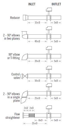
Figure 1: Typical straight run recommendations in pipe diameters (D) for vortex shedding flowmeters vary depending on the piping configuration.
A: Dr. Tódor von Kármán was fishing in beautiful Hungarian Transylvania when he noticed that the vortices formed by rocks in the stream were floating equal distances from each other, no matter how fast or slow the water was moving. This discovery became the basis of not only vortex flow metering, but also contributed to the advance of modern aviation and space technology. Simply stated, as long as the velocity profile is fully formed (the Reynolds number is over 20,000), the distance between the shed vortices is constant. This phenomenon is the same as the one that keeps the wavelength of the fluttering of flags a simple function of the diameter of the pole, unchanged by wind velocity.
Now coming to your questions: As to the IDs of the pipe and the meter, your sizing may be wrong because (in my experience) the meter ID, if properly sized, is usually at least one size smaller than the ID of the pipe. In any case, the K factors of vortex flowmeters are calibrated in schedule 40 pipe. There is a small K-factor shift if the pipe ID is different, because to the slight change in the velocity at the inlet, but these changes have been programmed in to the electronics and will be corrected for automatically when the user's pipe ID is other than schedule 40. The units are also tested for process fluid temperature variation and for upstream and downstream disturbances. As a result of this testing, compensation factors are included in the vortex meter software. This allows the output of the vortex meter to be adjusted for the actual process temperature and process piping being used.
Now, coming to the question on straight runs, if you are using a Rosemount 8800 meter, the meter accuracy increases (the shift in the K factor drops) as the length of the straight run increases, because that helps to fully form the velocity profile.
The Rosemount recommendation of 35 diameters upstream straight run is just an average. As shown in Figure 1, these requirements vary with the type of installation.
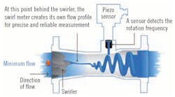
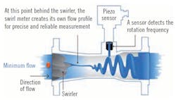
If you have a tight piping situation, remember that there are two types of vortex meters, and only the vortex shedding design requires long straight runs to form its uniform velocity profile—the vortex precession (also called swirl) meter does not. This design combines the characteristics of turbine and vortex meters in the sense that helical vanes at the entrance introduce a spinning (swirling) motion, resulting in the vortex precession. Thus, the meter speeds up the incoming flow and creates its own velocity profile (Figure2).
Because it speeds up the incoming flow, it can be pipe size, can operate at lower Reynolds numbers (10,000 instead of 20,000 minimum for the shedding design), higher viscosity (30 cp instead of 10 cp), higher rangeability (30:1 instead of 20:1) and shorter straight runs (3-5 D upstream and to 1-3 D downstream). Its accuracy is also claimed to be slightly better: 0.75% of rate instead of 1% for the shedding version.
Béla Lipták
[email protected]
Figure 2: In a vortex precession flowmeter, the frequency of swirl precession is proportional to flow. Source: ABB
A: Excessive pressure drop is rarely an issue; only for certain very specific process fluid conditions (e.g., marginal flashing or degassing service). It is highly unusual to select a vortex meter the same as the line size; usually it is one line size smaller (sometimes two line sizes). This should be checked using the vendor sizing software (most vendors have online versions you can use). Having too large a vortex meter can result in not being able to measure low-range flows.
Vendors now have inbuilt reducers. As an example, a 2-in. vortex can have 3-in. flanges to bolt directly to a 3-in. pipe.
When you order a vortex meter, you need to specify pipe size and schedule. The vendors have different vortex ID for the same pipe size and different schedules.
The mismatch between pipe and meter ID can cause noise interference for the vortex, giving faulty readings. The worst arrangement is when the vortex ID is smaller than the pipe ID. You should clarify with the vendor that their meter software can compensate for this (by filtering).
You only need to calculate straight runs using nominal pipe sizes; you are wasting time and effort calculating to two decimal points. You will not be able to measure any significant difference. Use the pipe size because you are trying to establish the ideal flow profile before it reaches the vortex flowmeter—this is based on the pipe size, not the vortex size.
Upstream and, to a less extent, downstream obstructions disturb the ideal flow profile (e.g., an elbow). These flow profile disturbances give +ve or -ve flow measurement offsets. The amount and polarity depend on the type of physical obstruction and distance between the obstruction and the vortex.
The errors are offset and not inaccuracy measured as +/- tolerance of the measurement. Modern vortex meters can be configured to take these offsets into account. With this offset compensation done in the configuration of the vortex, you can install them with 5D upstream and downstream piping straight runs in many instances (if I remember correctly). The vendors have detailed information in their manuals.
Simon Lucchini, Retired chief controls specialist
Fluor Canada Calgary, [email protected]
A: Normally, the inside diameter of most flow transmitters as well as the flanges will comply with the pertinent pipe schedule for the pressures at which it will operate. For example, a 3-in. pipe that is 3.5-in. OD (88.9 mm) in Schedule 40 has the ID 3.068 in. (77.93 mm), and in Schedule 80, the ID is 2.9 in. (73.66 mm). Small variations in ID should not impact the equipment operation. The vendor will have to indicate the expected pressure drop across his instrument, and you need to consider it in the pipeline dynamic.
Normally, the method I prefer is to use the OD of the pipe or the nominal size of the line, since the ID will always be smaller depending on the pipe schedule. For example, a 2-in. pipe will have an OD 2.38 in (60.33 mm) and nominal size of 2 in. (50.8 mm), while the ID will be much smaller, so the optimal design condition would be to use 2.38 in. (60.33 mm), which would result in the 30D recommended by the manufacturer of the equipment being 71.25 in. (1,809.75 mm) and 5D it would be 11.88 in. (301.63 mm). This way, you are sure to maintain sufficient upstream and downstream dimensions. And, always round up to the nearest whole inch or 2 millimeters.
Alex (Alejandro) Varga
[email protected]
Latest from Flow

Leaders relevant to this article:
