
Just like a well-tailored suit, pneumatic conveying systems run efficiently and profitably if they’re properly designed, sized, integrated and configured. The key to a good fit in pneumatic conveying is the calculations used to size the system and other best practices for operating and maintaining it.
To help users develop and install a pneumatic conveying system that will best meet their individual requirements, experts from Kansas State University’s Bulk Solids Innovation Center (BSIC) provided sizing equations and other advice in a webinar earlier this year. The hourlong event, “How to: basic sizing of pneumatic conveying systems,” was presented by Todd Smith, business and strategy manager at BSIC, and Kevin Solofra, lab manager at BSIC, and hosted by Processing magazine.
All the right parts and points
“More specifically, we’re talking about sizing a dilute-phase conveying system, where the velocity of the air or gas is fast enough that all the particles are suspended in the gas stream,” says Solofra. “Dilute-phase is the most basic, simplest and easiest, so it tends to be the type that most users employ.”
When sizing a dilute-phase conveyor, Solofra reports the first fact users must determine is the minimum required conveying velocity, pressure and temperature, which can vary widely because there are so many different types and sizes of materials, which all have different shapes, densities, chemical and physical cohesion and other characteristics—along with specific conveying requirements that can be determined by calculation and testing. For instance, the pickup velocity for corn flour is 5,200 ft/min, but only 3,400 ft/min for wheat flour, while salt is 6,800 ft/min, and spaces can vary from 3,000 to 6,000 ft/min.
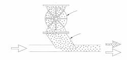
“You must be able to feed the material in through the airlock rotary valve or slide gate, and you really need to get that material to spread out and become dilute in that phase,” explains Solofra. “If the air velocity isn’t high enough, the material will settle, and build up until the pipe is blocked off. This is why it’s critical to know minimum velocity, along with pressure and temperature. For example, if you don’t stay close to minimum velocity, you could start with sugar granules, and end up with powdered sugar. If you have little PET plastic pellets, they’re round and will flow over each other pretty easily, so they’ll have a low conveying velocity. However, materials with a lot of fibers will tend to link together like bird’s nest and crate issues, so more velocity will be needed.”
Solofra explains there are many calculations available for addressing these issues and calculating the right velocity, but they’re mostly based on assumptions for a small set of materials. This can make them problematic to apply across wider ranges and types of materials, and can create up to a 200% error margin. This is why it’s also crucial to test materials and conveying calculations.
Get moving to pick up
While blowers and/or vacuums obviously do the work, it’s the pressure differences they create that actually produces the gas velocity and motive force that moves the materials in pneumatic conveying systems. While air is used most often, nitrogen or other gases can be used depending on the material’s requirements. Likewise, while some materials move better with a blower and pressure at the outset, and others move better with a vacuum at the end, Smith reports the equations and calculations needed for sizing are the same because the pressure differential is the same.
For instance, if a material requires a minimum velocity of 4,000 ft/min, this rate must be multiplied by the cross-sectional area of the pipe. If a 4-in. pipe is used, this means its area is 0.10 sq ft, so the minimum air velocity at the pickup point must be 400 cubic ft/min (cfm).
“In this case, we’re assuming the pressure is 10 psi,” adds Smith. “There are several ways to calculate this from textbooks, as well as one commercially available sizing calculation program called PneuCalc. Or, if we’re working with an existing system, then we can use a pressure gauge to measure the pressure at that point.”
Destination velocity and airflow rate
Meanwhile, at the destination and end of the conveying system, where pressure is 0 psi or close to it, Smith reports the well-known Ideal Gas Law is used to calculate air velocity and airflow rate (Q). In this example, its equation is:
P1 x V1 / T1 = P2 x V2 / T2
Where:
P = absolute pressure = gauge pressure + 14.7 psi
T = absolute pressure = gauge temperature in °F + 460 °F
V = gas volume
However, for pneumatic conveying, volumetric gas flow rate (Q) replaces the usual V, resulting in the equation:
P1 x Q1 / T1 = P2 x Q2 / T2
“The Ideal Gas Law shows, if we compress a gas or change its temperature, then its volume will change according to this formula,” explains Smith. “In our example, the only thing that makes this slightly complicated is you have to use absolute pressure. So, if we change pressure from one point to another, it's not OK to say we just changed it 5 psi. We have to know how much it changed relative to absolute zero. Since atmospheric pressure is 14.7 psi above absolute zero, we have to add it to the gauge pressure, which gives us the absolute pressure. Similarly, the absolute temperature is the gauge temperature plus 460 °F. The last item is gas volume, but in our case, we use volumetric gas flow rate (Q) instead. Using our new formula, if we know the gas conditions at one point, we can calculate the conditions at any other point.”
Using the adapted gas law formula of P1 x Q1 / T1 = P2 x Q2 / T2 for BSIC’s typical conveying system operating at 210 °F at the pickup point, gas conditions there are:
P1 = 10 psi + 14.7 psi = 24.7 psi
Q1 = 400 cfm
T1 = 210 °F + 460 °F = 670 °F
Meanwhile, at the destination, gas conditions are:
P2 = 0 psi + 14.7 psi = 14.7 psi
Q2 = to be determined
T2 = 670 °F
Solving for the airflow rate needed at the destination (Q2) means adapting the initial conveying formula as:
Q2 = Q1 x P1 / P2 x T2 / T1
Q2 = 400 cfm x 24.7psi / 14.7psi x 670/670
Q2 = 400cfm x 1.68 = 670 cfm
“It’s interesting that the airflow rate increases so much. It went up by 68% from 400 cfm at the pickup point to 670 cfm at the destination,” says Smith. “So, the air velocity required by the material at the destination is 670 cfm divided by the 0.1 sq ft cross-sectional area of the pipe, which results in 6,700 ft/min. This is a lot faster, which is important for understanding why elbows wear out faster at the end of a pneumatic system than at the beginning, It’s also important for sizing components at different points in the system, such as the filter at the destination, which will need to handle 670 cfm.”
Start your sizing
Once calculations are complete and gas conditions are known for the pickup point, destination or other locations in a pneumatic conveying system, users can size and specify the most suitable blower and other devices their system needs at each point.
To size the blower for its typical conveying system and determine its speed, Smith reports it must provide the 400 cfm required at the pickup point, but it will also need to deliver another 40 cfm to offset air leaks that usually occur when running a typical 10-in. airlock rotary valve feeder, resulting in a total of 440 cfm. Likewise, pressure calculation for blower sizing must include any other pressure drops due to obstacles during conveying, such as filters, aftercoolers, screens, diverter valves or other accessories. This may push the initial 10 psi needed at the pickup point to 10.5 psi at the blower.
Smith adds the most important sizing parameter is air volume at the blower’s inlet (Qinlet), which is also determined by using the adapted gas law formula of Q2 = Q1 x P1/P2 x T2/T1 to solve for Qinlet. This example uses a blower inlet pressure (Pinlet) of -0.2 psi and inlet temperature (Tinlet) of ambient, as well as a blower outlet pressure (Pout) of 10.5 psi, outlet temperature (Tout) of ambient plus 130 °F, and the outlet air volume (Qout) of 440 cfm. Using absolute temperatures and pressures:
Qinlet = 440 cfm x 25.2 / 14.5 x 540/670 = 616 cfm
“The blower inlet (Qinlet) is equal to the other point’s air volume (Qout) of 440 cfm multiplied by the ratio of the pressures, multiped by the inverse ration of the temperatures, which means the air volume at the inlet of the blower (Qinlet) needs to be 616 cfm,” explains Smith. “This is the number we’d use for sizing the blower’s model and speed.”
Similarly, feeders and other handling devices such as mixers and mechanical conveyors are sized based on volume and volumetric feeding rate of the material they’re expected to handle, rather than the gravimetric weight of that material. The conversion formula is volumetric rate = gravimetric weight / bulk density. For example, 200 lbs/min ÷ 40 lbs/cubic ft = 5 cubic ft/min. This guides the choice of what feeder model and speed is needed.
“So, if you want to increase that rate, speed up the feeder or get a bigger one,” adds Smith. “However, rotary valve feeders can rarely go over 30 rpm because the material can’t feed in well, so if more feeding is needed, that’s when a larger model is likely required.”
Rules of the (pneumatic) road
Beyond the calculations, Solofra adds its important to understand several rules of thumb when designing, sizing and implementing pneumatic conveying systems.
“Specifically, distance, pressure and rate are very proportional in all of the equations. So, if your distance doubles, then system pressure will need to roughly double. Or, if the distance doubles but the pressure doesn’t change, then the rate is inversely proportional and must be cut in half. Likewise, if you want twice the rate, then you’ll need twice the pressure, or you’ll have to cut the distance in half,” says Solofra. “Understanding these rules can help users avoid redoing their calculations from scratch when requirements change.”
Because everyone wants to increase conveying rates, especially in existing systems, Solofra reports it can be done by reducing the distance or number of elbows, which reduces pressure losses in the system. However, this often isn’t an option because many air sources, destinations and pipe paths are fixed, so two other choices are increasing pipe size or air velocity.
“If you increase pipe size, its cross-sectional area increases by the square of the diameter, while the material flow rate is approximately proportional to cross-sectional area,” says Solofra. “Two common pipe sizes are 3 in. and 4 in., so their cross-sectional areas are nine times and 16 times pi (π), respectively. This is a big factor because a pipe that’s just one inch larger almost doubles the cross-sectional area. You could also increase velocity and pressure, and just blow more air through to get the desired rate for the material.”
In addition, Smith reports that line size should be no smaller than four times the diameter of the largest particles. “This is easy for powders, but if you’re conveying rocks, pet food or styrofoam chips, they’ll crunch together and compact in the line. So, if your material is 1 in., you’ll need a 4-in. line,” he says. “It’s also important to avoid piping that inclines upward because material can more easily separate from the airflow, slide back down, get stuck, and causes pressure drops.”
Going round the bend
When considering conveying distance, Solofra adds it’s important that users know how much is horizontal, vertical or in between because conveying vertically can require up to twice as much energy as conveying horizontally. Similar resistance can also be reduced by minimizing the number of piping bends, avoiding back-to-back elbows that reduce pressure and velocity, and using long-radius that have the least pressure loss, instead of short-radius bend that can experience twice as much pressure loss. In fact, the pressure drop due to one 90° bend is equivalent to two 45° bands or three 30° bends.
“I’ve seen some systems with an obstruction, and the pipe goes 90° up, 90° over and 90° back down with just two or three feet of length between bends. This causes lots of unnecessary resistance and extra pressure drops, and it’s something to avoid,” explains Solofra. “Those are situations where it’s best to take the pipe up to where it’s clear, and take a straight, horizontal run. So, the smaller the number of elbows, the better you’re going to be.
“The difficulty with back-to-back elbows is they not only reduce pressure and reduce air velocity, but also cause material being conveyed to drop out of suspension when it hits the wall of the elbow. This means the material needs to reaccelerate, and wait until the airflow can bring it back up to speed, which typically requires 10 pipe diameters.”
To ease the passage of materials, Solofra reports that pneumatic systems typically use long-sweep conveying elbows. Long-sweeps have a centerline radius (CLR) of eight to 12 pipe diameters, while short-sweep elbows have a CLR of less than five diameters. For example, a long-sweep for a 4-in. pipe requires a 32-48 in. CLR that’s sufficient for conveying, while a short-sweep for a 4-in. pipe only has an 18-in. CLR that makes it suitable for an air-only section.
Solofra adds that flexible hoses shouldn’t be used in conveying lines, except for short distances. “This is because they have more wall friction due to plastic or rubber construction, and they often have hard, high-degree bends,” he says. “Plus, flexible hoses wear out more quickly than metal pipe, even if the conveyed material is soft.”