Orifice Rangeability
"Ask the Experts" is moderated by Béla Lipták, process control consultant and editor of the Instrument Engineer's Handbook (IEH). The 4th edition of Volume 3, Process Software and Networks, is in progress. If you are qualified to contribute to this volume, or if you are qualified to answer questions in this column or want to ask a question, write to [email protected].
Q: Currently we have a flow transmitter with orifice elements ranging from 0 to 10000 Kg/hr. However, we are planning to have a new flow that could vary depending on the heater mode. If it is gas, the flow will be 8000 Kg/hr, but if we change the mode to Admix (naphtha/propane mixture), the flow will be 1300 Kg/hr. Can we re-calibrate the transmitter for the lower range instead of changing the transmitter?
These transmitters provide the inputs to cracker flow control.
Hamed Afallah
[email protected]
A: The span of a properly calibrated smart d/p transmitter can have a turndown of about 100:1, at an error limit of 0.1% full scale (FS). If your transmitter is calibrated to read 100% d/p when the flow is 10000 kg/hr, it will read 1.7% of the d/p range (59:1 turndown) when the flow is 1300 kg/hr and less, if the flow drops further. With an inaccuracy of 0.1% FS, when the measurement is at 1.7% of the d/p range, the error in percent of actual flow will be 6%.
Assuming that even at the lowest flow rate, the flow is still turbulent (RE >20000) the flow coefficient will still change with flow, so your transmitter needs to be a "smart one" to correct for that. The Reynolds number is calculated by:
Re = 3160(SG)(Q)/(ID)µ
where ID is the inside diameter of the pipe in inches, Q is the volumetric liquid flow in gallons/minute, SG is the fluid specific gravity at 60 °F, and µ is the viscosity in centipoises.
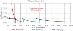
If your present transmitter does not have this 100:1 rangeability, or if you want better accuracy at low flows, you can stack and switch two or more transmitters (Figure 1) or switch orifice runs as the flow changes. The error contribution of the d/p transmitter is at least 0.1% full scale (FS), which corresponds to 1% AF at 10% flow, and 10% AF at 1% flow. Added to that is the error contribution of the plate. Therefore, if you can live with the above errors, and if you provide density compensation for the naphtha/propane ratio variations, and temperatures are constant, plus pressure variations are compensated, then you can use automatic switching of the spans of a multi-range smart transmitter or can switch the outputs of a stack of individual transmitters.
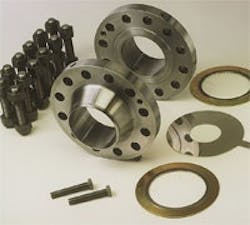
If between flow changes you can stop the flow (isolate the pipe), you can switch orifice plates by installing a manually or automatically operated two-orifice fitting to match the flows. If you must stay in operation while switching, you can install parallel pipe run(s). (See Instrument Engineers Handbook, Vol. 1, 4th ed., p. 275, Fig. 2.15u or www.controlglobal.com/1002_ATE.html.) The larger the number of parallel runs, the higher will be both the cost and the accuracy of the installation.
As to the total precision of the measurement, you have to consider both the error contribution of the plate(s) and that of the transmitter(s). The error of a correctly manufactured and installed orifice plate is about 0.5% of actual flow (AF) over a range of 3:1. Below that, the error quickly rises and can make the measurement almost meaningless. Therefore, if the error contribution of the plate is greater than that of the transmitter, switching plates will increase the accuracy more than switching of the transmitters.
Béla Lipták
[email protected]
A: The differential across an orifice varies as the square of the flow. Let's say your transmitter is calibrated 0-100 in., and that equals 0-10000 Kg/hr. At 8000 Kg/hr, you are reading 80% of scale, so your transmitter will read 64% of scale (64 in. wc) across the orifice [(0.8)2 = 0.64]. If your flow drops to 1300 Kg/hr, you are reading 13% of scale, and your resulting differential will be (0.13)2 = 1.7% of scale or 1.7 in. wc. Below that, the differential will fall off even more quickly.
Most transmitters claim a 100:1 turndown, so if you're currently near the upper end of your transmitter's range, you might be able to span it low enough to read the low flows. You might even be able to pick an orifice plate size that would allow the same transmitter range to read the complete range of flows, though your measurement would likely be noisy at the low flows, and the orifice would generate a high pressure drop at the upper flow rates.
Other options include:
- Swap the orifice plate for a smaller one when you're running the lower flow rates. (If the line is not easily isolated, you can install an orifice fitting that would allow you to swap the orifice plate in run.)
- Leave the orifice plate and install a second low transmitter in parallel with your existing transmitter. (You can use the same taps and static tubing.) This allows you to read the high and low flow rates, and your control system can be programmed to automatically select between the two, depending on the flow reading.
- Consider a different flowmeter that has a linear output (unlike an orifice plate). That will give you better turndown and allow you to measure the flow accurately throughout the range of interest.
Hunter Vegas
[email protected]
A: The quoted change in service is typical of gas pipeline flows and was addressed long ago. From the problem statement it sounds like this is gas to a burner. The reference to "admix" sounds like the gas composition may vary with time. It all comes down to the value/cost of the changes versus the value/cost of improved measurement.
Whatever the cost of a commercial solution, it will most likely be less than the time the plant people will waste chasing, and trying all sorts of ideas.
Among my concerns are the change in flow coefficient with Reynolds number with the wide change in flow. I would have to reconsider the quoted error resulting from the orifice plate. In the typical industrial installation, the uncertainties caused by the pipe ID, coupled with uncertainties from the loose tolerance in typical orifice flange bolts, are not low.
The accuracies quoted in the standards do not address uncertainties in the installation.
Cullen Langford, PE
[email protected]
A: Around 1970, a nitric acid process required a 100 to 1 turndown to cover the air and ammonia flows from start-up to production rates. Failure to maintain the combustion ratio was penalized by blowing $1 million worth of platinum gauze catalyst into the heat exchangers. If you got too cautious, the fire went out, and you had to start over.
The proposed solution was to use a precision position transmitter on a V-Ball valve that was calibrated for flow versus position at a constant 100 in. of water drop across the valve. During start-up, running on the 400 Hp steam turbine and not the 7000 HP expander, we found that we couldn't stabilize the interaction between the air flow controller and the valve pressure drop controller.
Finally, we added a mechanical stop to the V-Ball for a fixed, low-flow orifice and another for high flow. This worked fine for both ammonia and air. Sorry, I don't recall how we managed the transition between ranges. This only had to work on the way up because a safety shutdown system was the only thing that stopped production.
I expect that modern computational control systems could have stabilized the interaction.
Bill Hawkins
[email protected]


