"OSHA doesn't tell you how to detect gas or how to alarm. It's up to your engineering group to make it happen." aeSolutions' Warren Johnson explained some of the finer points of gas detection system design at the 2019 Siemens Automation Summit.
In the course of satisfying the basic needs of modern society, industry must handle a broad range of hazardous substances that if not properly contained pose a genuine threat to life and limb. Escaping gases, in particular, can result in explosions and fires as well as acute and cumulative health effects for workers and surrounding communities.
In the United States, it’s the role of the Occupational Safety and Health Administration (OSHA) to set limits on employee exposure to toxic and hazardous substances, but it’s up to industry to ensure that those standards are met, said Warren Johnson, senior project manager for consulting, engineering and integration firm aeSolutions, in a presentation covering the essential aspects of gas detection system design at the 2019 Siemens Automation Summit.
“OSHA doesn’t tell you how to detect gas or how to alarm,” Johnson explained. “It’s up to your engineering group to make it happen.”
In addition to OSHA regulations, in particular 1910.1000 Subpart Z Toxic & Hazardous Substances – Air Contaminants, Johnson recommended the National Institute for Occupational Health & Safety (NIOSH) and the American Conference of Governmental Industrial Hygienists (ACGIH) as important sources of information and guidance.
“NIOSH is the primary authority on what the limits should be—they make recommendations to OSHA,” Johnson said. “We rely on NIOSH data to determine our gas detection philosophy,” he said of his work leading aeSolutions’ consulting practice in this arena.
A language of its own
As do most scientific and engineering pursuits, the detection and measurement of toxic and hazardous air contaminants has its own language and acronyms. Key definitions among these are:
- Time weighted average (TWA) is an average gas concentration over time
- Permissible exposure limit (PEL) is an eight-hour TWA
- Short-term exposure limit (STEL) is an acceptable average exposure over a short period of time, usually 15 minutes
- Ceiling value (C) is the exposure limit that shall at no time be exceeded. If instantaneous monitoring is not feasible, C shall be assessed as a 15-minute TWA
- Immediately dangerous to life or health (IDLH) is the atmospheric concentration of any toxic, corrosive or asphyxiant substance that poses an immediate threat to life, would cause irreversible or delayed adverse health effects, or would interfere with an individual's ability to escape from a dangerous atmosphere
- Equivalent exposure for a mixture (Em) refers to a calculated limit for a hazardous gas mixture
- Recommended exposure limit (REL) refers to NIOSH-specific recommendations
- Threshold limit value (TLV) refers to ACGIH-specific recommendations
The first step in the design of any gas detection system is formulation of a gas detection philosophy, if one’s organization doesn’t already have one, Johnson said. That framework will guide a whole series of more detailed design decisions once it’s determined which gases need to be detected and at what levels. Then it’s on to the choice of detector technology.
Detector selection & placement
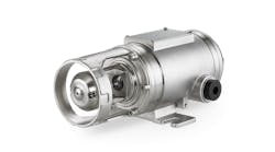
Fixed point gas detectors fall into three primary technology categories: electrochemical, infrared and open path, each of which has strengths and weaknesses.
Electrochemical, or catalytic bead, units work by catalytically oxidizing combustibles present in the ambient gas. This technology requires the presence of oxygen, and accounts for some 80% of gas detection applications, according to Johnson.
Infrared detectors rely on the absorption of infrared radiation by contaminant gases to do their job. This technology doesn’t require the presence of oxygen, and IR detectors tend to have a longer service life than do catalytic bead units. They’re also not susceptible to undetected failures due to catalyst poisoning, Johnson noted.
Open path detectors also work using infrared absorption, but across an open area rather than at a single point. These units effectively measure the average concentration along the entire length of the beam, so they can detect the presence of a contaminant, but may not discriminate a dangerous concentration.
Just where to place the detectors so that a hazardous leak does not go undetected is where the real design challenge begins. “Much of the published industry guidance on detector placement is focused around oil and gas applications, for methane and propane,” Johnson said. “Other industry verticals such as pharmaceuticals and specialty chemicals have a broader assortment of hazardous materials in play,” Johnson said. “Scenario-based modeling is the best approach.”
Scenario-based modeling is a complex undertaking in itself, but in short relies on a three-dimensional, computer-based model of the process area, including air flow patterns. The designer can then simulate emissions from identified leak points for a variety of opening sizes as well as process and ambient conditions. The resultant dispersion patterns—and necessary detection levels—drive system detector locations and count.
“The modeling gives customers and engineering teams the knowledge that they need,” Johnson said.
“We often vote gas detectors to avoid nuisance alarms,” Johnson added. “But at the same time, don’t over-instrument—detectors are often cross-sensitive to different compounds.”
Architectural aspects
Once detector locations are set, system design tasks turn to the wiring, control panels and human-machine interface aspects. “First, locate gas detectors and warning lights on a general arrangement drawing, then determine local and remote panel locations based on end-device locations,” said Johnson.
“Consider voltage drop when sizing cable and placing panels. Then, run power supply calculations to ensure panels can support the connected I/O loads. Remember that most gas detectors are three-wire instruments that draw 0.3 amps—not standard 4-20mA instruments,” Johnson said.
To ease integration tasks for its clients, aeSolutions offers a packaged gas detection system panel based on Siemens technology, including redundant S7-410-5T controllers, ET200SP HA I/O modules and SIVaaS (SIMATIC Virtualization as a Service) operating system. Historian, web server and Safety Matrix visualization tools are also available.
When it comes to local operator interface displays, Johnson recommended that all transmitters and warning lights be represented as animated icons that clearly indicate if there is a problem with the device (open circuit, short circuit or fault/diagnostic) or if the device is in bypass mode (taken out of service for maintenance). Device faceplate displays should include transmitter health and alarm status as well as historical trends, he added.


