Calibrating Injection Molding Machines, Compressor Control
“Ask the Experts” is moderated by Béla Lipták, process control consultant and editor of the Instrument Engineer’s Handbook. Co-authors are need for the preparation of the 5th edition. If you are interested in updating a chapter or sub-chapter, send me your resumé. If you would like to ask a question or join our team of “experts,” please write to me at [email protected].
Q: I am wondering if you know of any published info on the proper procedure to calibrate an injection molding machine (valve calibration that controls speed, position, etc.)?
A: I enjoy reading this kind of unique questions from your readers, though control application technology has changed in the digital age. I am not sure we are talking about the same kind of problem.
Several years ago I was looking for an answer for the same question in an injection molding machine in the development lab. Our application called for temperature control, multi-stage pressure and temperature differential control and, above all, composition control for a multifeed extruder. The second and third stages were temperature-sensitive to blockage of this polymer product. Though no published data was available at that time, [besides Perry’s handbook] the manufacturer’s literature gave us a starting point, and the commercial interest of my company prevented us from publishing our development work. However Werner Pfleiderer of Germany may have some of those control strategies in its publications. It is worth your time to investigate.
A: An associate built a PLC control system for an injection molding machine to make 54 “gummy” fishing worm lures per cycle. The ingredients were vinyl, glitter, color, salt, scent (shad or garlic). Color combinations were one color, half-n-half, variegated. The business required six machines running 16 hrs/day for a production of 56,000 “baits” per day. His contact information is Bruce Keen, 918.336.4369, or [email protected].
Robert E. Sherman
Consulting Technologists Ideagroup
Q: We often encounter the compressor control of air compressing or refrigerant compressing. Do both need anti-surge control (vent or recirculation)? Are there any other differences? In case of a multi-compressor with common suction and discharge line, is split-range control usually employed to balance load requirements?
A: I assume you are referring to centrifugal, not reciprocating or axial compressors. I also assume that your compressor drives are variable-speed. If that is the case, my comments are as follows:
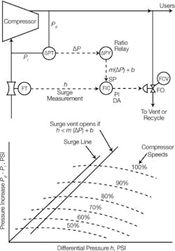
- Yes, centrifugal compressors need surge protection on both air and refrigerant services (See Figure 1). On air service, venting is acceptable from an environmental perspective, but you can save energy if you recirculate it. Refrigerant, on the other hand, should always be recirculated, both because of its value and environmental considerations.
- In common applications, there is no difference between air and refrigerant compression, but in cryogenic refrigeration (hydrogen, neon), there is. I am assuming your installation does not involve cryogenics.
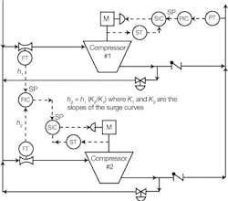
- If you have multiple compressors operating in parallel, the load among them can be balanced to keep them at equal distance from their respective surge curves (See Figure 2) or the load can also be distributed to always maximize the loading of the best efficiency unit(s).
- Because the operation of a compressor under surge conditions involves wasting energy, you can design your control algorithm to shut down one of the machines when a surging condition is approaching.
- If you experience surge conditions often and for extended periods, and particularly if the compressors are large, you should replace the let-down valves with expansion turbine generators to recover the let-down energy.
Béla Lipták
Figure 1. Compressor surge control
Q: Currently the oil and gas industry is hearing a lot about using WITSML (Wellsite Information Transfer Standard Markup Language) to transfer instrumentation data from remote sites to the office. What are the best and most efficient ways to transfer telemetry over satellites with high latency in near real time?
Glenn Warner
Chevron North America Expl and Prod Co.
A: The most efficient strategy for telemetry transmission is the one with the least amount of overhead needed to get the job done—no matter what the medium, satellite, wire or what. However, the best way is more involved and depends not only transmission effeciency, but on how you plan to use the transmitted data.
WITSML (I do not know a lot about it yet) seems to be mostly an attempt to put together a set of already standard protocols for Web/internet transmission and services specifically for the wellfield/gas and oil transmission industry. If you plan to use a lot of web-type services (for web page displays, forms and control panels), and you want interoperability between systems, WITSML has a good chance to become the “best way.”
Al Pawlowski, PE
Baton Rouge, La, USA
Q: I am getting enquiry for pressure release butterfly valve. Can you send me a conceptual drawing on its operation? What is meant by set pressure for release? What is the settable pressure range?
Kamlesh
DelVal Flow Controls
A: It seems that your client wants to use a butterfly valve instead of a regular, spring loaded pressure safety valve. This is not a good idea, because butterfly valves tend to leak, even if they are soft-seated. As to the installation, all you need is a fail-closed butterfly valve sized for the required relief capacity. The valve should be provided with a spring loaded, pneumatic actuator operated by a three-way solenoid valve. The solenoid is to be wired to a normally open high-pressure switch, which will close when the process pressure rises to the set point of the switch and thereby will energize the three-way solenoid. The energized solenoid opens the air supply to the valve actuator, thereby opening the valve. When the process pressure drops down below the “set pressure” of the switch, its contact opens, de-energizing the solenoid and venting the air from the actuator to close the valve.
The “pressure range” is the range within which the set point of the pressure switch is adjustable.
Béla Lipták


