Sound Wave Principles
By David W. Spitzer
The same is true for ultrasonic flow measurement. Wouldnt it be great if you could clamp a sensor onto the pipe and measure the flow through the pipe? Benefits would aboundincluding not having to shut down the flow or cut the pipe. Installation would be faster and easier. Unfortunately complications tend to get in the way of this smooth-flowing scenario.
Ultrasonic flowmeter technology falls into two general categoriesDoppler and transit-time. Early ultrasonic flowmeters used the Doppler effect to measure flow because Doppler signal processing techniques were more readily adaptable to the analog technology of the time. The development of transit-time ultrasonic flowmeters accelerated as microprocessor technology became more prevalent and cost-effective. Now only a handful of ultrasonic flowmeter designs currently use Doppler technology exclusively.
The Doppler Effect
The Doppler effect is characterized by a frequency shift that occurs when an object is moving towards or away from an observer. For example, an ambulance siren will sound differently when the ambulance is approaching an observer from when it is moving away. When the ambulance is moving closer, the waves emitted by the siren will tend to be closer together and, therefore, have a higher pitch (frequency). The frequency shift is proportional to the speed with which the ambulance is moving closer.
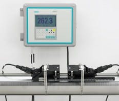
Figure 1. A small ultrasonic flowmeter with two traverses.
(Courtesy Siemens)
Transit Time
Transit-time ultrasonic flowmeters measure the amount of time the ultrasonic signal takes to travel upstream and downstream in the fluid. With no flow, these times are the same. In a flowing fluid, the ultrasonic signal will travel faster in the downstream direction. The fluid velocity is determined by analyzing the measured upstream and downstream transit times. Transit-time ultrasonic flowmeters mitigate the need for particles in the fluid. However, these flowmeters will not function when the ultrasonic path is broken because a fluid is excessively opaque to ultrasonic energy.
Some correlation flowmeters could be considered ultrasonic flowmeters because they use ultrasonic energy to sense the flow stream at two or more locations in the pipe. The distance between the locations and signatures are correlated to determine the fluid velocity.
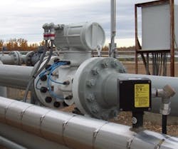
Figure 2. A transit-time ultrasonic flowmeter.
(Courtesy Emerson Process Management)
Ultrasonic flow measurement may sound straightforward, but there can be a number of complications. For example, how many and what type are the particles in the fluid? If there are too few particles, then the reflected signal may not be strong enough to process. If there are too many particles, then the measured velocity may measure the fluid velocity at the pipe wall and not represent the average velocity in the pipe. A distorted velocity profile also can adversely affect the measurement.
Ultrasonic flowmeters measure fluid velocitynot flow. Users want to know the flow ratenot the velocity. This may appear to be a subtle point because the flow can be calculated by multiplying the measured velocity times the cross-sectional area of the pipe. However, flow measurement accuracy can be affected by the uncertainty associated with the cross-sectional area. Some ultrasonic flowmeters have spool pieces that are tested in a flow laboratory to ensure a known relationship between the measured velocity and flow. Other ultrasonic flowmeters consist of a pair of sensors that the user attaches to the outside of pipe where the inside diameter and internal condition of the pipe may not be known accurately. In such an installation, the accuracy of the flow rate is questionable, even if the sensors can measure velocity with no error.
Ultrasonic flowmeters are available for pipe sizes range between approximately 6 mm and 10 m in diameter. Fluids include liquids, gases and multi-phase fluids, such as slurries. Ultrasonic flow measurement techniques can be used to measure the velocity of stack gas and flare gas. In general, sensors can be wetted or non-wetted (clamp-on). Wetted sensors tend to exhibit better ultrasonic connections with the fluid while clamp-on sensors are easier to install.
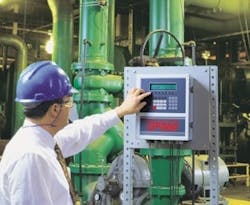
Figure 3. Clamp-on ultrasonic flowmeter
(Courtesy GE Sensing)
Be wary of Doppler installations located near radio antennas because their frequency of operation is approximately the same as that of AM radio stations. In one such installation, it was possible to listen to a local radio station on the test leads. That installation was a failure because there was no practical way to shield the instrument.
Doppler ultrasonic flowmeter applications include fluids with a solids concentrations between 100 mg/l and 30%. Solids size should be greater than approximately 75 microns, and the solids specific gravity should be at least three times greater than the carriers specific gravity. That is, the specific gravity of the solids alone (not the bulk density of the slurry) should be over three when flowing in water. Avoid stainless-steel tubing and high-density polyethylene pipe.
Velocity Matters
Regardless of the flowmeter technology, you should ensure that there is a good velocity profile in the flowmeter. Distorted velocity profiles can significantly increase measurement errors. Multi-path transit-time ultrasonic flowmeters are available to measure flows that exhibit non-uniform velocity profiles. Increasing the number of paths generally increases the accuracy with which the flow can be measured. It is advisable to use straight runs or flow conditioners to develop a good velocity profile for the flowmeter rather than increase the number of paths (and the cost). That said, in critical applications, such as for custody transfer, it is not uncommon to install a multi-path spool-piece ultrasonic flowmeter with lots of straight run in conjunction with a flow conditioner to achieve superior accuracy.
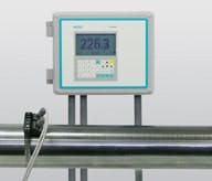
Figure 4. Clamp-on Doppler ultrasonic flowmeter
(Courtesy Siemens)
Be sure that the fluid itself is uniform in the flowmeter. Some fluids can separate when flowing in horizontal piping, so the top and bottom phases may travel at different velocities and cause measurement problems. Relocating the sensors in a vertical pipe section often resolves this problem.
Life would be simpler if there were fewer complications. Wouldnt it be great if you could clamp a sensor onto the pipe and measure the flow through the pipe? Ultrasonic flowmeters solve this problem in some, but alas, not all cases.
David W. Spitzer is a principal in Spitzer and Boyes, LLC, and can be reached at 845.623.1830 or www.spitzerandboyes.com.
For more information on flow technology go to www.controlglobal.com/flowmeter.html.
