Ask the experts: Differential pressure missteps

This column is moderated by Béla Lipták, automation and safety consultant and editor of the Instrument and Automation Engineers' Handbook (IAEH). If you have an automation-related question for this column, write to [email protected].
Q: I have the following questions concerning a conventional level detection differential pressure (D/P) transmitter which is installed above the upper pressure tap. Please see sketch of the application (Figure 1).
We have used a conventional D/P transmitter—not one with a diaphragm seal. The reason for keeping the transmitter above the top nozzle is to drain any condensate back to the vessel/tank. My questions follow:
- Can we the put level transmitter above the upper nozzle?
- Please help me to derive the equation of LRV and URV to be set when conventional D/P transmitter is kept above the above nozzle. I've seen a majority of level transmitters installed at lower nozzle or below the lower nozzle for head measurement. So, for this arrangement, what is the impact on calibration range when the transmitter is installed above the top nozzle?
- Is this arrangement, which does not include diaphragm seal, seal pot or purging, allowed per international standards such as API best practices?
- When there is 10% of liquid filled up, how will liquid create head on the transmitter (high pressure side)?
- How do we ensure that liquid head will be acting on the high-pressure leg all the time (without any vapor pocket) when the actual level inside the tank is 10-15%?
- How do we ensure that density of vapor will be the same on impulse tubing (particularly on low pressure side), so that the chance of measurement error will be minimized?
Jatin Katrodiya
[email protected]
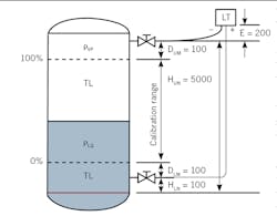
Figure 1: Condensate drain-back into tank by locating the level transmitter above the tank.
A1: The operating pressure creates serious problems. It's my experience that everything leaks; the only question is how much. It would be very difficult to keep the high-pressure sensing line filled only with gas.
Your scheme as shown will most likely fail to work even at startup. If the pressure was low enough, I would suggest a purge on both connections. That will require a compressed gas source. I would prefer to use remote chemical seals in this service.
Cullen langford
[email protected]
A2: You certainly have a non-conforming installation. Most installations locate the lower leg below the tank, and use diaphragm seals on both legs. Unless the “high pressure” (HP) leg is a filled tube with diaphragm seals on both sides, I don’t see how the high pressure from liquid level and vapor pressure can get to the level transmitter.
If your high pressure leg is diaphragm sealed and filled with an inert transfer fluid, it will appear to the level transmitter as the head (pressure) of the transfer fluid plus the head of the liquid in the tank plus the pressure head of the vapor space. The low pressure (LP) side will see only the pressure of the vapor space. When you subtract the HP pressure from the LP (the reading of the transmitter) you will have the liquid level in the tank plus the head of the HP leg. Since the HP leg is a constant, it can be removed by setting the zero point of the level transmitter. Now you should be able to do your math.
Dick Caro
ISA Life Fellow
[email protected]
A3: If for some reason you don't want to use chemical seals or purge both connections, but you do want the condensate to drain back into the tank, you can follow Figure 2 and reverse the output of the transmitter. Naturally, you have to correct for the density difference between that of the ambient temperature condensate and the density of liquid in the tank.
Béla Lipták
[email protected]
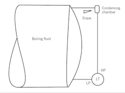
Figure 2: Seal-less D/P level measurement solution as often applied to boiling fluids.
Venturi vs. flow nozzle?
Q. Working as an instrument engineer in the oil and gas industry, I've specified a flow measuring device as an orifice meter, but while sizing with maximum beta ratio, the resulting permanent pressure loss is higher than what the process department allowed as the maximum allowable pressure drop. Hence, it's understood that orifice will not be suitable for this measurement purpose, and I'm considering some alternatives for the process conditions and line size. As an alternative to the orifice, in order to meet the process maximum allowable pressure drop, we decided to go with either a Venturi or flow nozzle primary element.
Now, I don't know which to chose. Can you suggest the factors or considerations in which a Venturi meter is preferred to a flow nozzle or vice versa? What are the basic considerations that have to be taken into account for selecting one or the other, and which is preferred and why so?
M. Ulangatham
Instrument Engineer
[email protected]
A1: In general, you want to use Venturi measurement when the range is small, say less than 100 in. H2O, and nozzles when you have a larger flow range. Most Venturi meters you'll calibrate for 0-10 or 0-25 in. H2O. Flow nozzles work basically as a restriction orifice (RO), so use the same basic principle.
Alex (Alejandro) Varga
[email protected]
A2: The flow nozzle is a preferred choice for steam flow measurement.
Debasis Guha
[email protected]
A3: This is a common question, so I'll give you a more detailed answer.
The meter coefficient of a typical orifice is about 0.62, while that of a Venturi or flow nozzle is almost one (0.99). Therefore, at the same ∆P and the same ß ratio (diameter of restriction divided by the pipe inside diameter), these meters pass about 40% more flow than an orifice.
The big difference between them is in their cost and pressure recovery. The cost of the Venturi is higher, say about $6,000 for an 8 in. cast iron one, while an 8 in. aluminum nozzle is about $1,200. At a beta ratio of 0.5, a standard Venturi recovers about 85% of its differential, while at the same beta ratio, an ASME flow nozzle only recovers about 35% of its differential. Consequently, because of the high pressure recovery of the Venturi, its operating costs are much lower. As a result, the savings in pumping costs can quickly compensate for the initial price difference.
Among the two, the Venturi is more accurate, about 1% full scale (FS), while the flow nozzle is about 2% FS. The rangeability of both is about 4:1. The straight run requirement of nozzles are longer (10-30 diameters) than Venturis (5-20 diameters), but not that much. Flow nozzles are available in a larger range of beta-ratio (0.3-0.7). And as far as installation goes, flow nozzles should be installed downflow when used on wet gases, wet steam or liquids with suspended solids, but neither meter should be used on slurries or dirty fluids.
With Venturi meters, cavitation can be a problem when the downstream pressure of a liquid drops below the fluid's vapor pressure. Bubbles form, and cavitation can destroy the throat of the meter. The bottom line is: because your process people are concerned about pressure loss, a Venturi should be used.
Béla Lipták
[email protected]
