Steam Quality Measurement; Automation Levels
This article was printed in CONTROL's September 2009 edition.
"Ask the Experts" is moderated by Béla Lipták, process control consultant and editor of the Instrument Engineer's Handbook (IEH). The 4th edition of Volume 3, Process Software and Networks, is in progress. If you are qualified to contribute to this volume, or if you are qualified to answer questions in this column or want to ask a question, write to [email protected].
Q: Would you be willing to share some of the available solutions for steam quality measurement. I am presently involved in a project which needs to measure steam quality from steam generators for SAGD steam injection.
Jim Balfe
[email protected]
A: Steam quality is the portion of the saturated steam in a saturated steam/water mixture. Steam quality of 0 indicates 100% water, while a steam quality of 1.0 indicates 100% steam. The measurement of steam quality is useful in determining the enthalpy of saturated water/steam mixtures, because the enthalpy of steam (gaseous state) is many orders of magnitude higher than the enthalpy of water (liquid state).
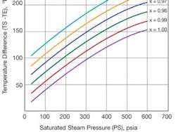
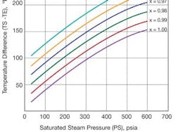
If steam temperature and pressure are known, the enthalpy can be obtained from steam tables or from grraphs, as shown above.
If the steam temperature and pressure are known, the internal energy (enthalpy) can be obtained from the steam tables (appendix in my handbook). The density of steam is also a function of its temperature and pressure. Therefore, by measuring the temperature and pressure, the density of the steam can be calculated, and if the volumetric flow of the steam is known, its mass flow (heat flow) can be also calculated.When steam is purchased for heating or to drive turbines, it is usually paid for on the basis of its enthalpy. The heat content of the steam drops as some of the steam is condensed, because energy is lost to both friction and to heat loss as it travels from the boiler to the various users. This loss increases due to insufficient thermal insulation of pipes, leaking joints on valves, pipes and other equipment, or long line lengths.
Steam quality can be measured by throttling calorimeters, which depend on constant enthalpy expansion for the measurement of the moisture content. It takes the steam sample through a throttling orifice into a well-insulated expansion chamber. There, by measuring the chamber temperature (TE), and using the saturation temperature (TSs) and saturation pressure (PS), the steam quality (x) can be obtained from Figure 1.
Béla Lipták
[email protected]
A: Google "Throttling Calorimeter." It will explain the principle of steam-quality measurement as well as provide links to commercial suppliers.
Greg Shinskey
[email protected]
Q: Is there any reference to explain what is automation Level 2 in detail? I need to know about the features, pros and cons of such systems in DRI plants.
B. Kamali
[email protected]
A: The numbering of automation levels varies a great deal, although ISA (88.00.01, S88) and IEC attempted to standardize it. In the processing industries, manual control is usually called Level 1, but others refer to on-off control as Level 1, and yet others identify fixed setpoint control as Level 1. These starting points (manual, on-off or set-point control = 1) demonstrate the levels of supervisory, unit and plant-wide optimization.
For digital communication applications, OSI (Open System International) defines seven layers, as you can see in the table at www.controlglobal.com/0909_ATE.
Béla Lipták
[email protected]
A: Perhaps Level 2 refers to the Purdue Enterprise Reference Architecture (PERA) by Dr. Ted Williams at Purdue (see www.pera.net/Ind_home.html).
In this model, the equipment is Level 0 and the automation that enables setpoint control is Level 1. Level 2 is supervisory automation that sets the set points of Level 1. Level 3 coordinates the activities of Level 2.
ISA S95 is built on the PERA model, but years of committee work have made it a little hard to recognize. Its original scope was the communication between PERA Levels 2 and 3.
ISA S88 (batch process control) was also influenced by the PERA model, but it produced a seven-layer physical model that has a Control Module at the lowest layer. A control module consists of equipment and the basic control necessary to automate that equipment. The module may be recursive, containing simpler control modules.
The next level is an Equipment Module that consists of control modules that can implement an equipment phase of a recipe procedure, but the definition may depend on who you ask. The third level corresponds roughly to PERA Level 2, except that it refers to the automation required for procedural control of a batch processing unit.
The S88 work is described in Batch Process Control by Hawkins and Fisher, published by ISA in 2006. You might get what you need from the standard itself (ISA 88.00.01, unless they've changed the numbering system again), but the last thing we did was to eliminate non-normative language (explanations) as required by the IEC in 1995.
The OSI model for digital communication popularized the use of seven layers for a model. That is why the S88 physical model does not have an eighth level.
Bill Hawkins
[email protected]
Q: I want to know the effect of not following the straight pipe/meter run requirements for the following flowmeters: orifice, magnetic, vortex, turbine, ultrasonic and PD meters.
Furthermore, I wanted to know if there is any general rule for Meter run requirements and whose flowmeter has the least meter run requirement?
A.J. Naji
[email protected]
A: Please refer to the flow meter selection table, which is reproduced from my handbook. The table lists the straight run requirements and other features of all the volumetric and mass flowmeters.
Béla Lipták
[email protected]
A: I would like to remind readers that there are research based consensus standards. ASME-3M and IEC 5167 address orifice meter installations. Straight-run requirements for orifice meters depend on several parameters. Most vendors of flowmeter products provide instructions for installation of their meters. Hopefully, these are based on research data.
Sometimes we wonder about claims of wonderful accuracy.
Cullen Langford
[email protected]
A: Probably the swirlmeter, or vortex precession meter, has the least required straight run because it is itself a flow straightener.
Walt Boyes
[email protected]
A: Check the ASME codes and/or those of the API. They have long ago solved this problem.
Ron Dieck
[email protected]
A: The only thing I might add is a brief description of why you need a meter run. The meter run requirements for a flowmeter is specified so that the flow profile passing through the meter is repeatable. This repeatable profile allows the meter manufacturer to make certain assumptions about the flow characteristic when they are converting the data from the sensors into flow. A meter can be installed with meter runs that are less than specified, but the accuracy of the reading will be impacted. The effect of some pipe upstream pipe configurations has been studied and can be compensated in some meters. However it is obviously better to install the meter correctly in the first place.
Hunter Vegas
www.avidsolutionsinc.com


