Key highlights
- The article shows how changing pressure tap configurations—corner, flange, vena contracta, radius or pipe taps—directly affects the flow measurement output.
- It cautions against blindly trusting flow calculation software that provides no guidance on tap placement.
Q: The software I use asks for pressure tap locations, but gives no guidance on what location is ideal for which application. Yet, if I change the tap locations, the algorithm gives a different flow measurement, even if nothing else is changed. The same happens if I change the assumed beta ratio (orifice bore diameter divided by pipe diameter). I would appreciate your guidance.
G. Balachandran, instrument engineer / [email protected]
A1: Greg Shinskey would have called such a software package one that operates on "garbage in, garbage out.”
The first study of orifice behavior was reported in 1913 in the Handbook of Natural Gas by the U.S. Geological Survey. More than a century later, orifice-based flowmeters are very popular. Today, their measurements are transmitted by a variety of sophisticated methods, including wirelessly. Their signals are displayed on fancy screens, and used by sophisticated, model-based control (MBC) loops. Yet, as this question shows, their very basics are still not fully understood.
If differential pressure (DP) flowmeters are calibrated and installed properly, the total error in the measurement will be about 1% upper range limit (URL) over a flow range of 3:1. For obvious reasons, some manufacturers advertise their accuracies as if they were better by giving accuracy values based, not on the URL, but on some lower value. Another way to overstate accuracy is by not mentioning that claimed accuracy is correct only if the meter is calibrated, otherwise it will not to be.
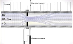
For these reasons, I will not limit my answers to the question concerning the options available for tap location options, but will also make a few additional comments using Figure 1.
The listings include:
Corner taps. In this configuration both up and downstream pressures are detected at the corners on the two sides of the plate. In the U.S., this design is used only if the pipe diameter is under 2 inches. In Europe, this configuration is popular for all sizes. However, in larger pipes, the upstream tap is often moved D = 1 inch upstream from the plate.
Flange taps. In the U.S., these are popular when the pipe diameter exceeds 2 inches, but not below. When used, both taps are located half the flange thickness from the orifice.
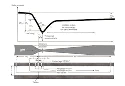
Vena contracta taps. The location of the VC point is the point where the diameter of flowing fluid is the minimum. This distance varies with the beta () ratio multiplied by the pipe diameter, which can range from beta = 0.35 D to 0.85 D. This is the distance between the upstream tap and the orifice. Because this distance is not constant but varies with the beta ratio, such taps can only be used if the pipe diameters exceed 6 inches because the tap location could fall under the flange.
Radius taps. These are tap locations that have both of their taps at half a pipe diameter (D/2) from the orifice plate. As such, distances don't change as a function of the location of the VC point.
Pipe taps. In this configuration, the upstream tap is located at 2.5 D, while the downstream one at 8 D. The measurement error of this configuration is about 5% greater than the other locations.
I asked some of the highly experienced members of my group of experts to also make their comments concerning this question
Béla Lipták / [email protected]
A2: This is a good question pointing out a possible weakness in software instructions. When we measure compressible fluids, it's necessary to correct for expansion of the fluid. The DP sensor knows only the difference across the primary element. If the operating pressure is much greater than the measured differential, then selecting upstream or downstream actually makes little difference. In real life, pressure is often not measured, but is assumed to be known and constant. It's important to correct the calculation if the operating pressure will change, or where the value of the flowing fluid is high. Some modern DP transmitters also report operating pressure, and some provide temperature measurement for density determination.
Cullen Langford, PE, instrumention specialist / [email protected]
A3: Flange taps located 1-inch upstream and downstream of the face of the orifice plate are the most common tap configurations recognized by American Gas Association (AGA) specifications. Corner taps at the face of the orifice plate are normally used in line sizes smaller than 2 inches. Pipe taps are usually located 2.5 inches from the orifice plate.
Get your subscription to Control's tri-weekly newsletter.
The upstream vena contracta taps are located one pipe diameter upstream of the orifice plate, and at the vena contractas on the downstream side of the orifice plate. They're not recommended when a variety of orifice bore sizes are required to meet flow requirements.
Alejandro Varga, senior engineer / [email protected]
A4: The pressure downstream of an orifice plate (or any restrictor) will recover from its minimum (vena contracta) to some portion of the upstream values. The pressure upstream of the plate will be a relatively constant (minus line loss) right up to the orifice. In other words, downstream tap location must be chosen closely to match the calibration in use, but upstream tap location normally doesn't need to be. It just needs to be in an area free of flow profile disturbance.
Al Pawlowski, PE, CEE staff, retired
A5: The ISO 5167.1:2003 standard uses density 1 at the upstream tapping, and for compressible fluids, uses the pressure at the upstream tapping (1) to calculate density. Some earlier standards used the downstream tapping point for the reference pressure, and some used an average value between 1 and 2. Naturally, the pressure location at 2 or pave gives a value that includes some or all of the ∆ from the flow through the orifice as well as 1. Consequently, the orifice coefficients differ, not only due to differences in pressure recovery depending on tap geometry, but also depending on the location of the reference pressure tap. You don’t have identical process parameters if you're measuring reference pressure at different points.
Ian H.Gibson, process, control and safety engineering consultant / [email protected]
This column is moderated by Béla Lipták, who also edits the Instrument and Automation Engineers’ Handbook, 5th edition, and authored the recently published textbook, Controlling the Future, which focuses on controlling of AI and climate processes. If you have a question about measurement, control, optimization or automation, please send it to [email protected]. When you send a question, please include your full name, job title and company or organization affiliation.
About the Author

Béla Lipták
Columnist and Control Consultant
Béla Lipták is an automation and safety consultant and editor of the Instrument and Automation Engineers’ Handbook (IAEH).

Leaders relevant to this article: