How to stabilize a hunting tank level
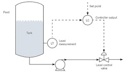
Q: I have a question; please guide me. In a level control loop, we have the following components: 1) the sensor/transmitter, 2) the controller and 3) the control valve (Figure 1). When such a loop hunts (cycles) when operating in the automatic mode, how do we eliminate the hunting? What causes it? And is there a standard that will tell us what to do? Is it the controller, the sensor-transmitter or the control valve that's likely to cause the cycling?
Waqar Ahmed
[email protected]
A1: A good question. There is no standard that would answer it, but books like Greg Shinskey's or my handbook analyze it in great detail. Below, I will give a brief summary of the causes and remedies of control loop cycling.
What your sketch shows is an intermediate storage tank (a "surge tank"), which is likely located between two processing stages of a plant. It probably serves the purpose of accepting whatever variable inflow (load) is sent to it from an upstream processing unit, and provides a more stable supply to downstream equipment. Naturally, in the long term, the quantity of fluid that enters has to leave the tank, but in the short term, if the level is allowed to rise and fall as the inflow varies, the surge tank will smooth out the load variations. In order to do that, the level must not be held at a fixed point, but must be allowed to float up and down. That being said, the fluid must float between limits, and not be allowed to overflow or run dry—between, say, a minimum of 20% and a maximum of 80% of the tank volume (a dead band). This means that some cycling will be present (dead-band control), but its period of oscillation will be long and its amplitude will be low.
If your level cycles excessively, that can be 1) because you're trying to keep the level at a fixed point and the load cycles due to some outside causes, or 2) the controller is badly tuned, or 3) the valve is sticking.
Outside causes: To narrow the possible causes of the oscillation, the controller should be put in manual mode to see if that stops the cycling. If the oscillation persists, it originates from outside the loop, so you should look at the upstream or downstream equipment to find the cause. In your case, this is unlikely, but in others, it can be caused by interaction with other control loops.
Bad tuning: Yours is a non-self-regulating and integrating process. Non-self-regulating means that the inflows and outflows are independent, and integrating means the change in the volume, V, in the tank is an integral function of the load (inflow, F, into the tank). Therefore, the time constant of this process equals V/F.
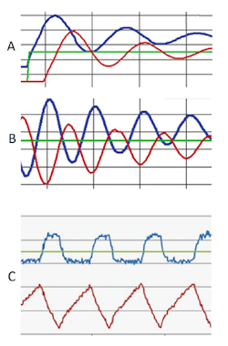
Figure 2: A) If Oscillation is caused by too much integral, after a step change in the set point (green), the valve opening (blue) peaks when the level (controlled variable - red) is at midpoint and vice versa. B) If oscillation is caused by too much gain, after a step change in setpoint (green), the maximum and minimum values of the controlled variable (level - red) and of the valve opening (blue) will coincide. C) Level (brown) will cycle in a triangular form if oscillation is caused by a sticking valve (blue).
Connecting two integrators (represented by the tank time constant and the integral setting, I, of the controller) in a closed loop produces an oscillator. Therefore, integral action generally isn't used in this application. If your cycling looks like the one in Figure 2A, the tuning has too much integral. (If a process is noisy, a little integral is okay.)
If after a step change in setpoint (green), your cycling looks like the one in Figure 2B, the cycling is caused by the controller being tuned with too much gain (narrow proportional band, or PB).
Level control processes are always integrating, linear, noisy, use linear valves, and their controllers are tuned with a PB of 5%-50% and an I of 1-10 minutes.
Sticking valve: When the valve is sticking, after a step change in setpoint the valve doesn't respond while the control signal is inside its "dead band" (blue in Figure 2C). As a consequence, the controlled variable (level - brown) response is triangular. If in your application this is the case, put a positioner on the valve, or even better, convert the loop into a cascade one with a fast-flow control loop as the cascade slave of the level controller.
Béla Lipták
[email protected]
A2: I'd start my answer by saying there are no shortcuts to experience. Secondly, as somebody once said, "You don’t get to be trained to do process control without being educated." There are no recipes, sorry. There are no standards that I know of, although there are procedures for fundamental troubleshooting.
First of all, level is different from any other process, so be cautious about a level control in manual. A problem with an oscillation can be originated in any of three areas: sensor, controller or valve.
Start by putting the controller in manual. Detune the controller to see if that stops the hunting. If it does, then tuning is the cause. Verify that the sensor and valve are correctly connected, and are working properly (e.g., the level sensor float isn't hunting, or the valve isn't hunting with the controller in manual).
About the tuning parameters—don’t worry. You can’t tune a loop out of an oscillation caused by a mechanical problem, a large filter time constant, or a long sampling time.
Sigifredo Nino
Process Control Consultant
[email protected]
A3: The problem of hunting in level control of a vertical tank is not uncommon. My experience is: 1) to look into controllability, such as changing the vertical tank to a horizontal one, and 2) investigate the option of nitrogen cover, which is applying pressurized nitrogen gas above the liquid level in the tank to dampen the hunting problem.
The hunting problem may or may not be due to instrumentation. It could be process related.
Gerald Liu
[email protected]
A4: Level control is usually a self-integrating system. If you're operating with P+I on the controller, there's a high probability that you have too much integral on the controller. The control will be stable without it. Put the controller in manual, and see if you can hold the level by hand. If the inflow differs from the outflow, the level will increase or decrease. Adjust the manual output until the level is close to stable (neither falling nor rising). Thereby, you've determined, where the controller output should be at that load (inflow).
Try proportional gain alone (about 2, PB = 50%) and switch to AUTO. It will probably stabilize the level at some point other than the setpoint. If so, your problem has gone away. You can now look to increasing the P (gain) to reduce the offset error. If the gain is less than 1, the valve will not be able to have full travel, so this is a bad choice. If the controller starts to cycle (at a higher frequency than you're currently seeing), the gain is too high. Halve it. You may be able to add a small amount of I once you find a stable gain to reduce the offset, which a proportional-only controller will usually have.
The above is predicated on the assumption that the sensor and the valve are properly working. If you can't control the level by hand, then the valve may be sticking. Check it.
Now go and read any basic control handbook to fully understand this phenomenon, and get full instructions on controller tuning techniques.
Ian H.Gibson
Process, Control and Safety Engineering
Consultant
[email protected]


