How to size and select your next pressure relief valve
A pressure relief valve (PRV) is a safety device designed to protect a pressurized vessel or system in case of an overpressure event. An overpressure event refers to any condition that would cause pressure in a vessel or system to increase beyond the specified design pressure or maximum allowable working pressure (MAWP). As relief valves are the last line of defense, they should be independent and highly reliable.
The relief valve is designed to open at a predetermined set pressure. As fluid is diverted, the pressure inside the vessel stops rising and will begin to fall. Once it falls to the valve's reseating pressure, the valve will close. The difference between set pressure and reseating pressure is referred as blowdown.
Similarly, equipment must sometimes be protected against an internal vacuum. In such cases, vacuum relief valves open at a predetermined low pressure limit, admitting air or an inert gas into the equipment to keep the pressure from going too low.
Types of PRVs
Pressure relief devices can be divided into two main categories, closing and non-reclosing (Figure 1). The closing type are further divided into spring-loaded and pilot-operated. Spring-loaded can either be conventional or bellows type, while pilot-operated can either be pop-action or modulating-action. Each of these is further divided on the basis of pilot type, either flowing or non-flowing. Non-reclosing types consist of buckling pins and rupture disks.
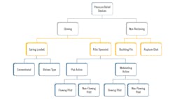
Figure 1: Pressure-relief devices encompass a range of technologies used to prevent dangerous over—or under—pressure conditions.
A variety of application-specific factors are considered when selecting PRVs. These include backpressure, service, discharge capacity and inlet pressure losses. Back pressure is an especially important factor in selecting the type of relief valve.
Conventional relief valves are used when the sum of the maximum variable superimposed backpressure plus the built-up backpressure is less than 10% of the set pressure. Bellows-type relief valves are used when the sum of the maximum variable superimposed backpressure, plus built-up backpressure, exceeds 10% of set pressure and up to the manufacturer-recommended limit. In practice, this is limited to 50% of the set pressure. If the backpressure increases more than 50%, then a pilot-operated relief valve should be used. Although pilot relief valves in theory can be used for up to 100% of the backpressure, in practice the backpressure should not increase more than 94% of the set pressure for reliable operation. This limit may vary for different manufacturers.
Pilot-operated relief valves have much higher discharge capacity compared to conventional relief valves of equivalent size. Also, due to availability of remote sensing line options, pilot valves can be used for high inlet pressure loss applications.
Set pressure and CDTP:
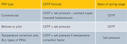
Table I: Different valve types require different cold differential test pressure, or CDTP, calculation formulas.
The pressure at which relief valve opens under service conditions is known as the set pressure, while the pressure at which he relief valve opens on a test stand is known as the cold differential test pressure (CDTP). As back pressure is not present during testing in the shop, it needs to be compensated for with a conventional relief valve. For bellows and pilot-operated relief valves, however, no adjustment is needed for the backpressure; CDTP and set pressure are the same. If the service temperature is higher than 250 °F, a temperature correction factor applies to all types of relief valves.
It's worth mentioning that spring selection for a conventional relief valve is based on the CDTP without considering the temperature correction factor. The CDTP formulas for different applications is shown in Table I.
For selecting relief-valve setpoints, two limits are considered. The upper limit is decided by considering the MAWP of the vessel/equipment being protected. As per ASME SEC-VIII, the relief valve shall not be set higher than MAWP of the vessel/equipment being protected. If MAWP isn't known, then design pressure shall be considered as MAWP. The lower limit is based on the maximum operating pressure of the system. The relief valve setting(s) should be at least 10% or 15-psig, whichever is greater, above the maximum operating pressure. Where unstable process conditions exist, this differential should be at least 10% above the maximum operating pressure or 25-psig, whichever is greater. The purpose of this margin is to avoid any immature activation of the relief valve. Refer to ASME SEC-VIII for details of these margins for different pressure limits.
Pressure definitions
Backpressure is the pressure that exists at the outlet of a pressure relief device as a result of the pressure in the discharge system. The total back pressure is the sum of superimposed and built-up backpressures.
Superimposed backpressure is the static pressure that exists at the outlet of a pressure-relief device at the time the device is required to operate. This is the pressure before the relief valve opens. Superimposed backpressure is the result of pressure in the discharge system coming from other sources and may be constant or variable.
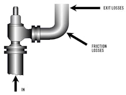
Figure 2: In addition to static pressure downstream of a PRV, built-up backpressure due to the dynamic discharge of fluids also must be taken into account.
Built-up backpressure is the increase in pressure at the outlet of a pressure relief device that develops as a result of flow after the pressure relief valve opens (Figure 2). This type of backpressure is caused by fluid flowing from the pressure relief valve through the downstream piping system. As built-up backpressure varies with the shape and size of the discharge piping, it's always variable.
Blowdown is the difference between set pressure and reseating pressure. It refers to how much the pressure needs to drop, below the set pressure, before a valve reseats. Blowdown happens because, when a relief valve lifts, larger disc area is exposed to system pressure, and it will not be possible for the valve to close until the system pressure has been reduced to below the set pressure. The design of the control chamber, or huddling chamber, determines at what pressure the closing point will occur. Proper blowdown helps in reducing the chances of chatter or seat leakage. Test facilities may not have sufficient capacity to accurately verify the blowdown setting. In such cases, the settings can't be considered accurate, unless made in the field on the actual installation and in accordance with the valve manufacturer’s specifications.
Relief valve inlet piping should be sized so that, at the combined maximum rated capacity of all operational PRVs, the pressure drop between the protected equipment and the PRV(s) shall not exceed 3% of the lowest PRV set pressure. The estimated inlet piping pressure drop should be also stated on the relief valve specification sheet.
Example calculations
Imagine, for example, an application with a PRV set pressure of 100-psi and 7% blowdown. The valve will close when the inlet flange pressure drops to 93-psig (100 – 7). Assuming inlet pressure losses of 3%, the system pressure at closing will be 96-psig (93 + 3).
Now, assuming that inlet losses are 10-psig, the valve will close at 103-psig, which is 3-psig higher than the set pressure. The valve will immediately try to open again, resulting in chattering and potentially damage to the valve. To avoid this situation, inlet pressure losses for any greenfield project should be limited to 3%.
It's worth mentioning that this inlet pressure loss criteria alone isn't sufficient to predict PRV stability. Additional factors that need to be considered include blowdown, relieving pressure and overpressure. Consequently, due to the complex nature of PRV instability behavior, a detailed engineering analysis should be performed as per API-520 for an existing installation, where inlet pressure losses are higher than 3%. This engineering analysis is referred to as a force-balance calculation. If the force-balance is passed and relief valves haven't shown any abnormal behavior or chattering previously, then inlet pressure losses higher than 3% may be acceptable.
Staggered setpoints
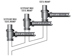
Figure 3: Staggering the set pressure of multiple pressure-relief valves prevents valve chattering and potential damage caused when valves attempt to open at the same time.
If multiple relief valves are being used to protect a vessel or equipment, then staggered setpoints are recommended. With this arrangement, the relief valve with the lowest setting will be capable of handling minor upsets, and additional relief valves will open as capacity requirements increase. This arrangement will avoid the chattering, as all relief valves will not open at same time. Staggered pressure settings also minimize emissions or product loss from relief valve operation.
For this arrangement, at least one of the relief valves shall be set at or below the MAWP of the vessel. The additional pressure relief valves may be set to open at higher pressures, but in no case at a pressure higher than 105% of the MAWP. In the example shown in Figure 3, the first relief valve is set at the MAWP of the vessel (100-psig), the second relief valve is set at 103-psig, and the third relief valve is set at 105% of the MAWP of the vessel.
It's also very important to know the correct backpressure at the outlet of the relief valve, as this will determine what type of relief valve—conventional, bellows or pilot—that's suitable for the application. Moreover, it will help to adjust the set pressure of the relief valve when being tested in shop. Selecting the correct set pressure of relief valves is also crucial, allowing enough margin between maximum operating pressure and the relief valve set pressure. This margin will help minimize the immature activation of the relief valves. The use of this staggering arrangement will help avoid chattering and emission loss. All of the above parameters, when correctly determined will make sure that the installed relief valves, which are considered as the last line of defense against unsafe conditions, are designed and operated in a way that will make facilities safe for operation.
References
- ASME BPVC SEC-VIII DIV-1 – Rules for construction of pressure vessels
- API-520 – Sizing, selection and installation of pressure-relieving devices
- API-521 – Pressure relieving and depressuring systems
- API-526 – Flanged-steel, pressure-relief valves
About the author
Farooq Ghulam is an instrument engineer working with Saudi Aramco’s, Process and Control Systems Department. He is an SME for pressure relief valves, surge relief valves, control valves and gas detection systems. He has more than 20 years of experience in the design, technical support, and maintenance of instrumentation and automation systems, and also teaches several courses, including pressure relief valves and control valves. He completed his MS degree in electrical and computer engineering at the University of Alberta, Canada, and BS in electrical engineering at the University of Engineering & Technology, Lahore, Pakistan. He is a registered Professional Engineer with APEGA, Canada, and FS Engineer with TÜV Rheinland. He can be reached at [email protected].
