All wound up
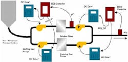
Greg: We feel like we have neglected all of our motor enthusiasts so this month we present an interesting case of the “now you see it, now you don’t” in terms of a cycle in series pump system submitted by George Bentinck, Chip Scavone, and Dave Schnelle. The system consists of pressure controllers at the inlet and outlet of parallel solution filters as shown in Figure 1 below. The inlet and outlet pressures are controlled by the manipulation of DC drives on individual stuffing gear pumps and metering gear pumps, respectively.
FIGURE 1: PUMP SYSTEMGeorge: A notable pressure limit cycle (~35% of scale at about a 30 second period) developed in the two pressures causing periodic process shutdowns or poor downstream product quality. Attempts at tuning (on-line and via simulation) and minimizing loop dead time by speeding up control logic execution yielded little improvement. The waveform appearance is similar to that seen with a “sticky” control valve - but this process does not use control valves, it utilizes DC variable speed drives and speed reducing gearboxes between the drive and gear pump. Drive tuning and performance checked and found OK by corporate expert. Acoustical analysis of gearboxes did not indicate defects. After months of living with the problem a pump motor developed a bad winding and was replaced. Pressure variability was greatly reduced to normal levels when the system was restarted with the new motor!
Greg: A positive displacement pump is a constant flow device, which means the pump curve is steep and process gain is high (small variation in flow causes a large variation in pressure). There is a limit cycle whose amplitude is proportional to the resolution limit of the drive (e.g. 0.2%) multiplied by the process gain. This combined with the interaction between pumps in series and parallel could lead to bigger oscillations. Beyond checking the A/D resolution of the input cards I am a bit out of my element here (final element humor) so I asked Bob Heider, who has much more experience in the ins and outs of motors, to take a look at the application.
Bob: I simulated the pump response for three different windings of DC motors to a step change in viscosity in a non Newtonian fluid. For “separated excited” winding, the peak change in flow was only 0.1 gpm versus 0.8 gpm for a “shunt” winding and 1.8 gpm for a “series” winding.
Greg: Windings of the wrong type or in bad condition could increase the effect of a process disturbance or load change to the point where it triggers sustained oscillations from resolution limits and interactions. Before we get all wound up let’s break for a twist and a turn by Stan.
Stan: We have been criticized for unintentionally, neglecting the mechanical aspects of control. This is probably because of our backgrounds and experience. However, we have been approached to consult with the Work 4 Company. They are in the process of developing sensors and controllers to properly tighten tops or lids on bottles, jars and other containers.
The question/problem is, “How Tight Should Tops Be Tightened (HTSTBT)?”
If lids are too tight, senior citizens, handicapped, people with arthritis and others with weak fingers find it extremely difficult or impossible to open a container. This then requires new appliances and gadgets to assist them. Some people will say, “Don’t tighten them so tight”. The manufacturers will then respond by saying, “If not tight enough, there will be leakage and spoilage by air getting into the container. Also, we need to prevent children from getting into the bottles and jars”.
We would like to help Work 4 Company design and build a Variable Tightness Top Machine or a VTTM. This is our initial design concept. A customer who enters a market goes up to a panel on the wall, enters their secret code, and turns a large dial that would look like a typical container top. This Variable Torque Dial or VTD would measure their hand strength and become the set point for the VTT Controller or VTTC. When their selection of items in the store is complete, the customer will go to the checkout counter and identify themselves by either entering their secret code or inserting a credit card. The cashier will scan the items for pricing as usual. Then the cashier, bagger, or customer will pass the jars and bottles through a Variable Torque Torguer or VTTR. The VTTR in conjunction with the VTD and VTTC will provide a VTT.
Another Problem: After the VTT is set, the sack packer or bagger cannot pick up the container by the top, which they have a tendency to do. Picking up the item by the top may negate the setting on the VTTR.
| PRESSURES BEFORE MOTOR REPLACEMENT | PRESSURES AFTER MOTOR REPLACEMENT |
| Metering and stuffing pressures before pump motor replacement (Y-axis scale = 80% of Span). | The same variables, on the same scale, after replacement of the metering pump motor. |
Editor: Since Greg has his time split playing consultant and going on vacation; we will need some kind of control algorithm for the VTTC. Stan is occupied adjusting the pH and the free and combined chlorine concentration of his salt pool. So don’t hesitate. Send in your educated guess. The winner will be invited to attend the first market to successfully offer this boom to weaker hands: custom-torqued tops!
Greg: We top this off with a list from Mark Sowell of the “Top Ten People You Would Like to See in a dunking Booth at the Company Picnic” and a puzzler from Hunter Vegas.
Top Ten People You Would Like to See
in the Dunking Booth at Your Company Picnic
10. The IT security person responsible for your company's password policy.
9. The Environmental Representative on your project.
8. The Accountant that won't let you use the current cost of natural gas to justify your project.
7. The Department Head that requires everyone to fill out a monthly time sheet.
6. The designer of your company's automated expense reporting system.
5. The Process Engineer that saved a buck by putting an actuator on a block valve.
4. The Operator that calls you in to tune a loop whose output is saturated.
3. The Project Manager that notifies you that the configuration work you were asked about last year needs to be downloaded tomorrow.
2. The Manufacturing Engineer that blames the spill on your multivariable controller that was not in service because the Operator had everything in manual.
1. The Engineer rolling out the new corporate interlock guidelines.
|
This Month's Puzzler: Hunter: The plant installed large 4-in. flange integral pad type DP level transmitters on several tanks. Each DP meter used a 25-ft.capillary and a 2-in. flange pressure pad on the low side of the meter to compensate for tank vapor pressure changes. The plant had to constantly recalibrate the zero on the meters every time they emptied the tanks and were considering installing a differential manufacturer's transmitters to eliminate the problem. Will wholesale transmitter replacement solve their problem? |


