Better protection from wildfires
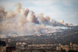
Several questions have been asked concerning the fire-fighting water supply problems that occurred during the recent wildfires in California. Rather than comment on each separately, I’ll describe the overall system that existed, and outline the many corrections that can be made to update any similar fire protection system.
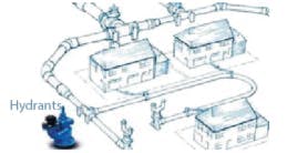
A1: The city water infrastructure in the Pacific Palisades section of Los Angeles was undersized. It was built decades ago, and sized to serve normal water needs of the area or small fires in individual homes (Figure 1). It wasn’t built to simultaneously provide fire-fighting water to several areas, particularly not under the conditions brought on by global warming.
During the recent wildfire in the Pacific Palisades area, the demand for water was at least four times more than the available supply. The high flow rate created high-pressure drop in the undersized pipes. Since the Pacific Palisades rise to more than 1,500 ft above sea level, supply pumps had to overcome the elevation. Correctly located water storage tanks should usually be in zone increments of about 100 feet of elevation between each. Because of all these factors, by the time the water reached the hydrants in parts of the Palisades area, its pressure could have been below the required, 20-psig minimum.
In these areas, water was supplied from three tanks, each with about 1 million gallons of storage capacity. It’s not clear if they were supplying water one at a time or simultaneously, but they ran out of water one at a time in about four-hour intervals. Therefore, it’s fair to assume that the average water demand rate was about 1million/(4 x 60) = 4,200 gpm. I don’t know what the maximum water makeup rate to the three tanks was, but because the level was dropping in the tanks, I know it was less than 4,200 gpm. The makeup water to these tanks was pumped from various reservoirs, probably under manual control.
The total system consisted of the pumping stations at the reservoirs generating the inflow to the supply tanks, the tank level controls, and the pumping station feeding the main pipelines from the tanks up to the hydrants in the protected areas and the hydrants themselves. How were these blocks designed, what was wrong with them, and how can they be updated by applying the process control rules?
State-of-the-art hydrant design: Most hydrants were undersized (Figure 2, red size category), nearly a century old, wharf-type units, with one 2.5-inch outlet connection and a more than 100 psig pressure rating. They were installed before color-coding or the 0.25% lead-free requirement was established for fire-hydrant components.
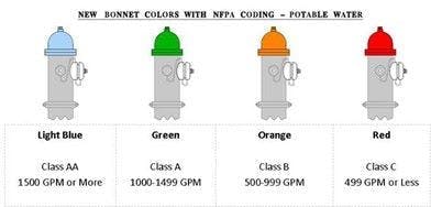
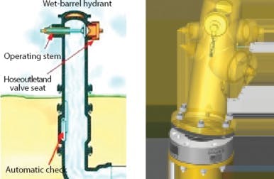
In my view, the old hydrants should be replaced with those with following design: if freezing temperatures don’t occur in the Los Angeles area, I recommend using wet-barrel hydrants with multiple outlets, each provided with manually operated, hose-shutoff valves with externally operated stems (Figure 3, left). This would make sure to only open outlets connected to hoses that are in use. These new hydrants should be sized for a maximum flow capacity of 1,000 gpm (Figure 2, orange cap). As to the sizes of the outlet connections, I’d use multiple 4-inch Connections, instead of the single, 2.5-inch connections in the old hydrants. This would allow more than one hose to be simultaneously connected to the hydrant.
As to the connection to the main water supply pipe (Figure 3, center), I’d provide a gate-type, shutoff valve. At the bottom of each hydrant, I’d add an excess flow-check valve, so that if a hydrant is sheared or its outlet is left open—which probably occurred in Los Angeles—the excess flow-check valve (Figure 3, right) would close. This design guarantees water isn’t spilled, and the water supply to the other hydrants isn’t stopped.
Probably the most important change I’d make is adding inexpensive, wireless, solar-powered, pressure monitors, which are similar in design to those used to monitor air pressure in car tires. These wireless detectors provide an overall display of the total water distribution system in the area’s monitoring center, and let anyone with a mobile phone check the status of all hydrants.
State-of-the-art water supply design: The water storage tanks should always be designed with low-level alarms, which ring in the fire monitoring center whenever the level in the tank is below 90%.
If the storage tanks aren’t located at a higher elevation than the hydrants, they require pumping stations to send the water up to the hydrants' elevation. The stations consist of two, carefully sized, variable speed pumps, which are tracked in the monitoring center. The speed of the master pump should be throttled by the pressure controller, which maintains an hydrant inlet pressure of around 30 psig. If the speed of the master pump increases to 90%, the secondary (also variable speed) pump starts, and the hydrants’ supply pressure controller throttles the speeds of both pumps. A clamp on, ultrasonic flow detector measures the total flow. The secondary pump stops when flow drops below 90% of the master pump's capacity.
It’s important that all monitoring and control signals be wireless because strong winds can damage any wired data transmission (Figure 4). The fire protection system must continue operating if its regular power supply is lost. Therefore, backup power storage is required, which is continuous and large enough to operate the system for several days. Diesel or battery backup doesn’t meet this requirement, including in the Los Angeles area. Solar power stored in batteries or hydrogen can be the energy choice if space is available.
Béla Lipták [email protected]
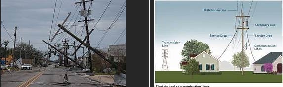
A2: During high-wind events, the power must be shut off to prevent sparks from the lines. Once the power is shut off, there’s no pumping of water from storage resources to desired locations. Also, communication lines and wireless data transmitters are typically mounted on towers that support the overhead power lines. In the event of a fire or other catastrophic event, not only power, but also communications might be lost (Figure 4).
Victor Wegelin, PE, automation consultant andcontributor to Instrument and Automation Engineer's Handbook / [email protected]
About the Author

Béla Lipták
Columnist and Control Consultant
Béla Lipták is an automation and safety consultant and editor of the Instrument and Automation Engineers’ Handbook (IAEH).

Leaders relevant to this article: