In process facilities, there are many valves in use. Some are for controlling the process, while others are used for process safety as part of a safety instrumented function (SIF). These SIFs are functionally independent and together compose the safety instrumented system (SIS). Some non-safety process valves are critical as well, in that their failure could result in an abrupt shutdown of the process—a spurious trip.
The focus of this paper is directed at these safety-related or critical valves and their proper operation. From a production prospective, the operation of these valves is a major concern, addressing operational availability (spurious trips) and safety availability (fail to function on demand). Both must be considered to achieve optimal production, process safety performance and reduce overall risk.
The safety function (SIF)
An SIF typically consists of three active components: the sensor, the logic solver and the final element. The valve is part of the final element, which also includes the valve controller and actuator (Figure 1).
Figure 1: The final element includes the valve as well as its actuator and controller.
These components function in series: the valve controller operates the actuator, which in turn positions the valve. It should be noted that the final element contributes more than 50% of the total probability of failure on demand (PFD) of the SIF, and its safety integrity level (SIL) is determined by its lowest integrity component. As such, it's a major source of dangerous (fail-to-function) failures.
Most corporate general engineering practices (GEP) spend a lot of verbiage on the valve and the actuator, providing detailed discussions on related topics, such as materials of construction, sizing, flow rates, pressure drops, torque requirements, maximum allowable stem torque (MAST), etc. Regrettably, little attention is paid to the valve controller and its importance in the safety performance of the final element. Needless to say, the valve and actuator could be appropriately sized and paired, but neither will function if the valve controller fails. Its importance should not be minimized because it's the Achilles Heel of the SIF.
In addition, SILs are listed and defined in many GEPs, but never referenced in the context of the valve controller or its internal components. Apparently, the valve controller isn't comprehended as a SIF component, and as such there are no safety-related requirements—or performance requirements of any kind other than being housed in a stainless-steel enclosure. It's too often relegated to the plant engineering personnel to design, build, approve and safety certify the valve controller. An independent safety certification is not required!
Failure modes and failure rate data
Pneumatically operated valves typically use solenoid operated valves (SOV) to control the flow of a plant’s instrument air supply (IAS) to the actuator, which in turn positions the valve. Typically, this SOV is of the normally closed (NC) type, and de-energizes to trip (DTT). An SOV is an electromechanical device, with multiple failure modes. The most common failure modes are coil failure (burn out) and/or a spool that is stuck open due to long periods of time operating in the open position. A coil failure is a safe failure, usually resulting in a spurious trip of the process. The stuck-open spool, however, is a dangerous failure, which inhibits the venting of the actuator, and prevents the valve from closing and achieving a safe state during an emergency shutdown demand. It should be stressed that a dangerous failure of the valve controller is a dangerous failure of the final element, and consequently the SIF. As such, SOVs in continuously open service must be fully cycled regularly via online testing, preferably without disabling or bypassing its associated SIF.
Having relevant SOV failure rate data is essential. Typically, the failure data provided by a manufacturer is based on continuous operation (failures per million cycles). For process applications, where the SOV remains in the open (energized) state for extended periods of time, this data isn't valid and should not be used for analysis of its safety integrity. To obtain safety-relevant failure rate data, a failure mode, effects and diagnostic analysis (FMEDA) must be performed on the SOV to determine its failure rate under low-demand/on-demand conditions. The resulting failure rates will be in failures per unit time, rather than failures per cycle.
Typically, an FMEDA provides two sets of failure-rate data. One set is without any testing, and the second set is with periodic testing. A comparison of the two data sets reveals that the dangerous undetected failure rate is dramatically reduced by periodic testing, when performed at a frequency greater than 10 times the expected demand rate. It should also be noted that plant failure rate data (based on usage in the facility) is typically not an acceptable alternative, unless collected in accordance with the provisions of the ANSI/ISA 61511 (S84) safety standard.
On-line testing of SOVs
To prevent a covert dangerous failure due to a stuck-open SOV, it's imperative to provide online, full-cycle testing (manual and/or automatic) of the SOVs. During testing, it's essential not to interfere with any inherent safety functions or cause a spurious trip of the process. The stuck-open failure is caused by o-rings on the SOV spool. These o-rings are used as internal seals to manage the air supply traveling through the SOV. When the o-rings are pressed against the SOV’s metal body for long periods of time (especially in a hot environment), they become sticky and impair the movement of the spool. Consequently, SOVs in continuously energized (open) operation must be fully stroked regularly via online testing to prevent a stuck-open failure, which inhibits the venting of the actuator and closing of the valve during a demand. It's also possible to test the valve and actuator online in what's called a partial stroke test (PST), preferably with pneumatic stops. Partially stroking the valve confirms that it's not stuck in place, and that its movement is not impaired. When PST is seamlessly integrated into a fail-safe, fault-tolerant valve controller, it provides a complete testing platform. (A comprehensive discussion of this topic is provided in the third reference cited.)
The requirement for online SOV testing to reduce risk is obvious and well-documented, but there are some options about how to configure it. If the objective is to keep the related SIF fully functional during the maintenance repair time (and it should be), then the SIF can't be bypassed or disabled during this period. As such, some level of SOV redundancy must be incorporated, and may be required as an architectural constraint per the ANSI/ISA 61511 (S84) safety standard.
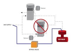
Figure 2: Online, independent testing of redundant solenoids may or may not be possible and could cause partial venting of the actuator and closing of the valve. If this presents an operational concern, then bypassing the SIF will be necessary to perform online testing.
A simplex configuration (single SOV) must be bypassed to be tested (or repaired) online. While bypassed, the valve controller is completely isolated from the SIS and its associated SIF. The valve is likewise isolated, and can only be operated manually.
A redundant design (two SOVs) has two options: only one SOV is active or both SOVs are active. In the case of a single active SOV, testing is accomplished by periodically switching between SOVs, and testing the inactive (backup) one. The procedure can be manual or automatic (testing performed via SIS logic). If a failure is detected, the SIF must be bypassed to perform the online maintenance repair, the same as required for the testing and maintenance repair of the simplex configuration. Another concern is the ability of the single active SOV to respond in a timely manner to a coil failure. If one occurs, this configuration must detect the failure, disable the active SOV, and enable the inactive SOV—all before the actuator vents and the valve closes, causing a process upset or spurious trip. For smaller or fast-acting valves, this will be a more significant problem.
For the case where both SOVs are active, both of the SOVs must be tested online independently. Depending on the configuration, this may or may not be possible, and could cause partial venting of the actuator and closing of the valve. If this presents an operational concern, then bypassing the SIF will be necessary to perform online testing, given that independent testing of each SOV isn't possible otherwise. Figure 2 illustrates how a complete bypass of the SIF can be implemented.
Once online testing is completed and the failure has been identified, it's time to perform the on-line maintenance repair. In most cases, maintenance repair is only possible if the SIF is bypassed and the valve controller is completely isolated from the actuator and the valve. A much lower risk scenario would be to bypass the failed SOV only, keeping the valve controller and the SIF active and fully functional during online SOV testing and maintenance repair. Doing so eliminates two maintenance issues as well. The first is having to use a stem clamp, or bypass the valve controller, and revert to manual valve operation. Second is the need to have maintenance personnel remove the stem clamp, or the bypass of the valve controller, upon completion of the maintenance repair.
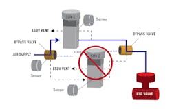
Figure 3: In this configuration, a bypass pneumatically isolates the failed solenoid, which can now be replaced on-line without disabling the safety instrumented function.
A new approach
This second-generation approach to online testing of SOVs in the valve controller is simple and easy to perform, and can be completed with the push of a button. Further, a manual bypass pneumatically isolates any failed SOV, which can then be replaced online without disabling the SIF (Figure 3). Likewise, note that the SIF is fully active and able to respond to a safety demand. The valve controller is fault-tolerant, having a hardware fault tolerance of 1 (no spurious trips), and is validated by comprehensive built-in diagnostics. When used to perform SOV testing at regular time intervals, it virtually eliminates sticky o-ring failures, thereby dramatically reducing risk and increasing the safety integrity and availability of the SIF. This second-generation implementation makes it possible to achieve that goal.
In conclusion, the fundamental objectives for safe, reliable valve-controller operation are as follows:
- Keeping the SIF fully active at all times (no bypassing);
- Eliminating dangerous, undetected SOV failures;
- Minimizing false trips due to SOV failures;
- Simple online testing of each SOV independently;
- Easy online maintenance and repair of SOVs; and
- Support for both manual and automatic on-line SOV testing.
How safe is your valve controller? The bottom line is it's always better and safer to test rather than to guess.
References
- ANSI/ISA 61511:2018, Functional Safety – Safety Instrumented Systems for the Process Industry Sector
- Improving Reliability and Safety Performance of Solenoid Valves by Stroke Testing, Loren L. Stewart, Julia V. Bukowski, Ph. D., and William M. Goble, Ph. D., exida
- Lawrence Beckman, Ph.D., TÜV-FSExp – SIS, “Test safety valves safely,” Control, March '18, p. 35.
About the author
Dr. Lawrence Beckman, P.E., TÜV FSExp-SIS, is president of SafePlex Systems Inc., Houston. He has published numerous papers on process safety, simulation and control. He is a senior member of the ISA, NFPA and AIChE; a voting member of the ISA SP84 safety committee; a registered professional engineer in Louisiana; and a TÜV-certified functional safety expert (116/06) and instructor.


