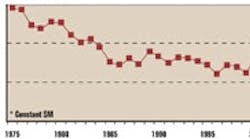
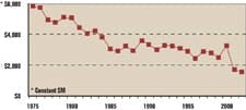
While power generation capacity capacity continues to keep up with demand, investment in transmission assets has not kept pace. In fact, investments in transmission assets have been in a steady decline for many years, steadily undermining the grid’s reliability. Consequently, any drop in supply reliability is surely going to impact power quality.
The overall lack of investment has been linked to how energy production and energy transmission is regulated in the U.S. Since its inception, the U.S. power grid has grown as a patchwork of regional transmission networks regulated by local, state and federal authorities. According to Bill Gould, executive director of the Electric Power Research Institute (EPRI) in an ABC News.com interview “The electricity system in this country has operated on the most part on 1950s technology. There are probably lines in cities nearly 100 years old.” Upgrading the aging infrastructure isn’t going to be cheap either—EPRI estimates it’s going to take more than $100 billion to make the necessary improvements.
Ways to Cope Now
But how can processors, and more specifically, plant engineers tasked with specifying or maintaining processing system motors and drives cope with declining power quality—something that’s likely going to be a fact of life for the foreseeable future?
A recent interview with Robert Glickman of ABB’s Electrical Systems Consulting group and Tom Bernhardt, principal engineer within the ABB Inc., Low-Voltage Drives business unit revealed insight into the power quality problems pulse-width modulation (PWM) AC motor control drive technology users are likely to encounter and the design features of this technology that can minimize their effect.
According to Bernhardt any power problem that reveals itself as a voltage, current or frequency deviation and potentially causes equipment failure is a concern to processors. “It’s important to determine the overall impact on a drive, the distance to the fault, and the impedance of the system upstream of the fault.” He says it’s equally important to understand the feeder impedance, the transformer connections between the faulted system and the electrical system bus. Let’s look at each of these conditions:
Voltage Sags
Utility system faults frequently are asymmetrical, single-line-to-ground faults that produce voltage sag, says Bernhardt. Voltage sags are a momentary decrease in rms voltage magnitude for typically ½-30 cycles, or 8 ms-1/2 sec. These sags normally are described by their magnitude and duration. But they also need to be understood in terms of the voltage imbalance, non-sinusoidal wave shapes and phase-angle shifts that accompany them.
“AC drives have considerable capability to ride through a voltage sag, because they store energy on their DC bus capacitors and can make use of the energy stored in the load’s inertia. The drive’s line voltage is monitored at the DC bus. Its control logic and fan power is taken from that bus. Therefore, the drive is independent of line voltage sag as long as the dc bus holds up. The DC bus typically will trip on under-voltage at an equivalent line voltage of 65- 51% of nominal rated voltage.”
On its own, explains Bernhardt, the DC bus can deliver full power to a load for about one cycle or 16 ms by allowing itself to decrease from its nominal voltage. As the bus voltage drops, the drive regulator adjusts the PWM pulse width to make up for the reduced magnitude of the output voltage waveform of the inverter. Alternatively, the drive could allow the motor speed to decrease and use the energy stored in the inertia of the load to maintain bus voltage. Typically, more energy is stored in the load’s inertia than the DC bus, making it possible to hold bus voltage for a longer duration--approximately ½-5 sec. says Bernhardt.
Wye-Delta Transformers
Both Bernhardt and Glickman point out that transformer connections have an interesting effect on the ultimate line voltage seen at the load during an asymmetric fault. Most AC drives are fed from a three-wire delivery without a neutral. As a result, the input rectifier stage only sees line-to-line voltages. At the fault location, a single-line-to-ground fault will yield a voltage of zero on one phase to neutral voltage, but the other two phases are essentially unaffected. If a wye-delta transformer is between the fault and load, then two of the phase voltages on the delta side affected by the fault go to zero, but none of the line-to-line voltages go to zero. The drive will see a voltage sag on two of the line voltages. Similarly, a line-to-line fault will cause phase shifting and can cause a zero voltage condition on the secondary of a transformer.
Phase Imbalance The phase imbalance that is associated with voltage sag is caused by the difference in the inductive reactance to resistance (X/R) ratios of the source and the faulted feed, and by the propagation of voltage sags due to single-phase faults through a transformer.
During normal operation, the input voltage to a drive is balanced and the diodes in the bridge rectifier are symmetrically forward-biased. A phase imbalance acts to lower the magnitude of one or more line-to-line voltages, reducing the peak voltage for one or more phases below the nominal capacitor voltage. This causes the rectifier diodes not to forward bias. In this state, no energy flows from the AC mains to the capacitor. The capacitor will continue to discharge until there is an input voltage peak that is high enough to forward-bias the diodes.
“Because the capacitor has discharged more than its normal amount, the current drawn from the AC mains to recharge it to peak voltage will be quite high, says Bernhardt. “ In fact, the rms input current on some phase might exceed 200% of normal rating, and the associated peak current drawn in the high-current phase may be as much as four (4) times the normal current.”
Under these conditions, explains Glickman, an AC drive often will trip on over-current, because the line current was too high; or, on under-voltage, because the DC bus dropped below some threshold.
“Similar effects will be seen when single-phase loads are unevenly distributed on a processor’s 3-phase power system.” Says Glickman. “The solution is to balance these loads more evenly across all three phases, or install an AC line reactor at the AC drive that is experiencing problems. The reactor should be sized to carry the drive’s full load current, and it should have an impedance rating anywhere from 2% to 6%,” he says. According to Glickman and Bernhardt, single-phase input operation of drives for a short duration is usually not a concern. But, continuous single-phase input operation will require that the drive be de-rated or sized by two or more times the actual power requirement because single-phase current is 1.87 times three phase current for the same power.
Line Impedance
The effect of utility impedance on the operation of a drive is a function of how stiff or soft the line is. “Nominally (i.e. %Z = 1%), the drive short circuit current is set at 100 times the drive rating,” says Bernhardt. “On a soft line (i.e. %Z > 10%), the short circuit rating is 10 times the drive’s rating; and on a stiff line (i.e. %Z < 0.1%), the short circuit rating is 1,000 times the drive’s rating (limited only by fault interrupting limits).”
Loading variations within the user facility are a second source for impedance issues say the two. When facility loads are energized, especially loads that have high inrush currents, excessive impedance will cause voltage sags and the effect on a drive is the same as discussed earlier.
Bernhardt and Glickman say there are a number of design techniques system designers can employ to minimize the deregulating effect of line impedance. “It is generally more productive to make impedance improvements, where possible, in the highest impedance components, such as transformers and long conductor runs,” says Glickiman. Some recommended practices include:
-
Avoid using multiple transformers to achieve proper load voltage,
-
Select low-impedance or oversized transformers,
-
Design long cable runs at the higher voltages, and
-
Increase conductor size above the minimum ampacity required by thermal design.
Voltage Transients
Capacitor switching is a common event on most utility systems note Glickman and Bernhardt. Shunt capacitors are applied on transmission systems, distribution feeders and at substations. These devices adjust the line voltage for differences between daytime and night time loading and may be switched on a daily basis. Energizing these capacitors causes a transient voltage between the capacitor and the power system inductance.
Voltage transients also are caused by line switching of heavy loads, such as large motors, without the use of soft switching, switching power factor correction capacitors, welding equipment, clearing line short circuit faults and lightning strikes. “Voltage transients are sudden, one-shot, sub-cycle voltage disturbances of tens to hundreds of microseconds in duration and could be over 1KV,” says Glickman.
Voltage Swell or Over-Voltage
Voltage-source PWM drives use a DC capacitor to smooth the rectified line voltage and act as an energy source for the inverter section of the drive, explain Bernahrdt and Glickman. Line voltage to the drive is monitored at the DC capacitor or bus. Over-voltage trip points are normally set at 130-135% of nominal rated voltage. An over-voltage trip inhibits drive operation, but does not remove the drive from the line. “By regulating the motor voltage via PWM modulation,” says Bernhardt, “the automatic restart function of the drive can be programmed to recover from an over-voltage trip, once the normal line condition is restored.”
Ground Placement
Drive power circuits are usually floating with respect to ground except for MOVs and EMI/RFI filters, say Glickman and Bernahrdt. They explain that ground reference can be at any potential at, or within the line voltages. EMI filters should only be used on symmetrical grounded neutral systems. “Much of the published literature related to power quality suggests that a high percentage of power quality problems are, in fact, related to wiring issues within the user’s facility,” notes Glickman, “with specific reference to grounding and bonding.”
AC Drives and Power Conditioning
Both Glickman and Bernhardt note that power line disturbances cannot be avoided totally. Different solutions exist to mitigate voltage, current and frequency deviations that are produced by the utility system. A number of low-voltage devices exist that have the capability to deal with a range of power quality conditions either fully or partially, but according to them AC drives, in their own right, should be viewed as a power conditioning technology. The degree to which the technology can correct for power quality conditions they explain, is largely a function of the design of the drive and the ratings of its semiconductors.
The interview concluded with Berhanrdt and Glickman offering a set of recommended protective-functions and ratings that, if followed, will likely provide processors with improved drive performance when power quality conditions are present at the drive input. It is recommended that users specify
- Phase-to-phase and phase-to-ground line voltage transient protection with a broad voltage operating range. Glickman and Bernhardt recommend a range from 65-130% of nominal voltage.
- Power-loss ride through, utilizing kinetic energy recovered from the rotating mass.
- Ground testing at the factory to 2,500 V rms power circuit to ground with MOVs disconnected.
Recommended Ratings
Specify drive components with high voltage stress ratings:
1600 PIV rectifier diodes; and
Line-to-line and line-to-ground Metal Oxide Varistor transient protection rated 120 to 370 joules, up to 8000 amp max, providing up to 160,000 watt absorption at the rectifier voltage rating for 1 to 2 milliseconds.
Glickman and Bernhardt point out that as MOVs have only a 1-2-watt, line-to-line power rating, care must be taken to avoid subjecting the MOVs to a continuous string of transients.
“An effective way to eliminate nuisance tripping is to isolate the drive from the power system with series inductors (chokes or line reactors),” says Glickman. “The additional series inductance of the choke or line reactor reduces the magnitude of the voltage transient. ABB drives have 3% line reactors on drives > 60HP and equivalent 3% to 5% bus reactors on drives 60 hp and below,” adds Bernhardt.
For processors to get the best out of their drives Bernhardt and Glickman recommend the following specifying tips:
- Specify control power operation down to an equivalent line voltage of 95VAC.
- Specify rated power without speed reduction to the load for up to 15 ms before tripping occurs during brownouts and full power outages.
- Specify current ratings at 110% for 1 min. (out of 10); 180% for 2 sec. (out of every 60); and 350% instantaneous over-current trip.
- Specify frequency variation with a 47-63 hertz tolerable range and rate of change > 10 hz/sec.

Leaders relevant to this article:


