QUESTION:
I HAVE a problem to control latex (pure rubber mix with acids) temperature inside Batch Reactor. The previous equipment was pneumatic and has now been converted to electronic. Because our controller can't perform auto tuning, we have to tune it manually. Our customer is not satisfied with current readings on chart paper where oscillation is too high and over-responsive. Please advise us how to perform manual tuning for cascade control processes.
Our customer also said that control valve response is too fast. They want measurement close to the set point, with the valve responding slowly (closed or open) until both readings are the same. What happens when measurement exceeds the set point?
Zulkefli bin Zakba, Project Engineer, Foxboro (M) Sdn Bhd
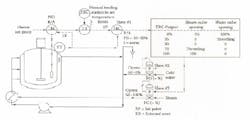
From the brief description you gave of the present behavior of your system, a simple cause of the cycling could be the dead band of your steam valve, which can be caused by dirt buildup on the valve stem. This can be fixed by cleaning the stem, or if you don’t have a positioner, placing one on the valve. The positioner should have a gain of 20 or more (PB=4-5%), and the actuator should be strong enough to provide it. A slightly more complex cause of limit cycling can be an interlock (which many batch reactors have) that prevents the opening of the steam valve after the initiator or catalyst is added to start the reaction. This can cause a limit cycle because the addition of the initiator can cause a drop in temperature. If the master TRC is prevented from correcting, it’s integral will wind up and could cause a limit cycle. It is one of the reasons why we always provide external reset, as shown in Figure 1 below.FIGURE 1:If your cycling is not caused by the above reasons, it could be caused by the hierarchy of speeds of the three loops of your cascade system. It is essential for good operation that the speed (dead time plus time constant) of the inner loops be much faster (if possible an order of magnitude) than their outer loops. This means that the valve must respond faster than the slave TRC, and the slave TRC must be much faster than the master TRC.If none of the above is the case, than start looking at retuning the master.Tuning
As to the cascade loop, I will concentrate on tuning the TRC master and will treat the slaveTRC as if (from the master’s perspective) it was part of the control valve. When visiting plants, I only check the positioner gain, which must be around 20-25 (proportional band of 4 or 5%), and set the gain of the slave TRC to ¼ of that (gain = 5-6 or PB = 15-20%). If the slave measurement is noisy, I do not use the I mode at all and usually do not use the D mode either (if the measurement is noisy or if the loop speed is fast enough as is). If neither is the case, I put in a few seconds of derivative, but only on the measurement, not on the set point.Now, in order to control the cooling phase of the batch process, we have to match the dynamics of the master PID controller to the dynamics of the process. The dynamics of any process can be described by at least three parameters: Gain (Kp), Time constant (T), and Dead Time (Td). Open Loop Tuning of Non-Interacting PIDs
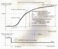
The process gain (Kp = K/?m) in your case is the % temperature change resulting from a 1% change in valve opening (coolant flow). In case of a chemical reactor, this gain drops as the load (reaction rate) increases because the heat transfer area of the reactor jacket is fixed and, therefore, the efficiency of heat transfer drops (Kp drops) as the load rises. You want to compensate for this drop in Kp by using an equal percentage valve (=%), which increases its gain (Kv) as the load rises. This way the KpKv product stays relatively constant.The PID control loop gain in the product of four gains: Process Gain (Kp), Valve Gain (Kv), Sensor Gain (Ks), and gainsetting of the controller (Kc, which is the P in the PID). We usually tune the gain (proportional band) of the controller (Kc) to obtain ¼ amplitude damping of the loop’s response to a load upset. This means that after an upset, we want (after each cycle) the amplitude of the oscillation to decay to one quarter of the amplitude in the previous cycle. To obtain this rate of decay, the product of the four gains (Kp.Kv.Ks.Kc) has to equal 0.5. In open loop tuning of self regulating processes, when the reactor is operating in a steady state, the PID master of the cascade loop is switched to manual and a step change is manually introduced into its output, manually reducing (or increasing) the coolant valve opening. This step increase or reduction in the heat input results in a reaction curve (a drop or rise in reactor temperature), which describes the dynamics of the process. The steady state gain of the process is the ratio of the % increase (or decrease) in temperature per % decrease (or increase) in coolant flow (K/?m). The time it takes for the reaction curve to reach 63% of its final value (0.63K) is the sum of the dead time (Td) and time constant (T) of the process. The split between these times is obtained by the intersection of a tangent drawn to the inflection point of the curve. The slope of this tangent is the reaction rate (A/T). Based on these readings, the Ziegler-Nichols’ recommendation for the correct settings, can be calculated, by using the equations listed in the Figure 2 below:FIGURE 2:
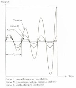
In this tuning method, the goal is to determine the gain or proportional band that causes sustained, un-dampened oscillation (Ku or PBu) and to measure the corresponding ultimate period of that oscillation (Pu) by measuring the time it takes for one cycle of the sustained oscillation to be completed. The tuning test is performed by first setting the dynamics of the PID master to zero (integral time to infinity/repeat, derivative time to zero) and set the proportional at the expected normal value. Or if that is not known, at 100%. Wait for the process to stabilize. When the temperature is constant, introduce an upset by moving the set point up or down (whichever is safer) by 2% for a minute and then return it to its original value. This upset will result in one of the curves shown below. If the response curve resembles A (un-stable, runaway oscillation), the gain is too high (PB too narrow). If it looks like C (stable, damped oscillation), the gain is too low. In either case, the controller gain is adjusted until a state of sustained, undamped, sinusoidal (not limit cycle) oscillation is reached.Once this state is established, one reads the ultimate proportional band that caused it (PBu) and the period of this ultimate oscillation (Pu).FIGURE 3:
Béla Lipták, Ask the Experts Moderator
THE MANUAL tuning of temperature cascade loops for chemical batch reactions is one of the most interesting control challenges. I devoted some 200 pages in my handbook to the various aspects of it. Here, obviously, I can not cover the topic to that depth, but I will try to give you a brief summary. I should first mention that the tuning I will describe is only for the exothermic (cooling phase) of the batch reaction. As you know, the batch process has several stages. I will not cover the heat-up phase, the switching from heat up to cooling, endpoint detection, or stripping controls.ANSWER:
Continue Reading

Leaders relevant to this article:


